
Page 182 - Analysis and Design of Energy Geostructures
P. 182
Deformation in the context of energy geostructures 155
where the body force components in the r; θ and φ directions are denoted by R ; Θ
and Φ .
Very often, the following formulation of the indefinite equilibrium Eq. (4.38) is
found
r σ ij 1 ρg i 5 0 ð4:42Þ
where g i is the gravitational acceleration vector, representing a particular type of body
forces. In elastic problems, it is often possible to omit body forces because their effect
can be superimposed based on the principle of superposition.
Together with Eq. (4.38), for an element of a material in equilibrium, the principle
of balance of angular momentum needs to be verified. Working with the mathemati-
cal formulation of the balance of angular momentum and that of linear momentum
yields to Eq. (4.12). When Eqs (4.12) and (4.38) are satisfied at all points of the mate-
rial, together with the equilibrium equations written for the boundary of the material,
the required conditions of equilibrium of the material as a whole are fulfilled, with the
resultant of the contact forces balancing the resultant of the body forces.
4.7 Boundary conditions
4.7.1 General
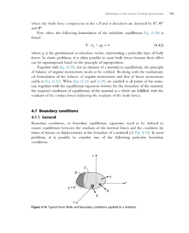
Boundary conditions, or boundary equilibrium equations, need to be defined to
ensure equilibrium between the resultant of the internal forces and the condition (in
terms of stresses or displacements) at the boundary of a material (cf. Fig. 4.10). In most
problems, it is possible to consider one of the following particular boundary
conditions.
Figure 4.10 Typical force fields and boundary conditions applied to a material.