Page 162 - Analysis and Design of Machine Elements
P. 162

Analysis and Design of Machine Elements
                   140
                        Steps              Computation                                   Results  Units
                        6. Confirm initial  From Eq. (6.30)  )
                                                    (
                        tension, F  0            P ca  2.5     2
                                           F = 500
                                           0     zv  K a  − 1 + qv
                                                  8.25  (  2.5  )         2
                                           = 500 ×          − 1 + 0.105 × 7.59 = 139 N
                                                 7 × 7.59  0.92
                                                                                         F = 139  N
                                                                                          0
                        7. Compute the force  From Eq. (6.31)
                        acting on the sheave            1           150.9 ∘
                        shaft, F           F = 2zF sin  2  = 2 × 7 × 139 × sin  = 1884 N
                                                 0
                                           Q
                             Q                                        2
                                                                                         F = 1884 N
                                                                                          Q
                                                                                         Select solid sheave
                                                                                         for driving sheave,
                        8. Structural design  D = 100 mm
                                            1
                        of V-belt sheaves  D = 355 mm                                    and spoke sheave
                                                                                         for driven sheave
                                            2
                       6.5 Installation and Maintenance
                       At installation, the two sheaves are first moved closer to facilitate belt assembly. The cen-
                       tre distance is then increased to a designed value to generate initial tension in the belt.
                       A proper amount of initial tension must be well maintained. An excessive initial tension
                       shortens belt life and overloads bearings and shafts, while insufficient initial tension may
                       cause slippage and generate heat and wear, which may also reduce belt life. Besides, belts
                       stretch permanently and loose initial tension after a period of service. Therefore, a belt
                       drive must have provisions to allow for belt adjustment and replacement.
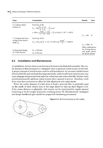
                         When the centre distance of a belt drive is fixed, a grooved idler is preferably used
                       on the inside of slack strand close to the large sheave to take up slack (Figure 6.13).
                       If the centre distance is adjustable, belt tension can be maintained by regular manual
                       tensioning or by the weight of pivoted, overhung motor [9]. Manufacturers’ catalogues
                       and design handbooks give details for proper belt-tensioning procedures.

                                                           Figure 6.13 Belt tensioning by an idler pulley.
   157   158   159   160   161   162   163   164   165   166   167