
Page 160 - Analysis and Design of Machine Elements
P. 160
Analysis and Design of Machine Elements
138
6.4.3.8 Compute the Force Acting on the Sheave Shaft, F
Q
For proper design and installation of shafts and bearings, it is desirable to determine the
force acting on the shaft mounting the sheave. From Figure 6.7, the force acting on the
sheave shaft is calculated by:
a 1
F = 2zF sin (6.31)
0
Q
2
6.4.4 Design of V-Belt Sheaves
V-belt sheaves should have uniformly distributed mass, a highly furnished groove sur-
face and be lightweight. For a high-speed sheave, the inertia force must be well balanced.
Materials used in a sheave include cast iron, cast steel, aluminium, Ultra High Molecu-
lar Weight (UHMW) polyethylene and so on. Cast iron is used for sheaves with a rotating
−1
speed less than 25 m s , while cast steel is recommended for higher speed and alu-
minium and UHMW for light-duty drives.
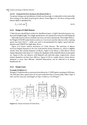
Figure 6.12 shows various structures of V-belt sheaves. The selection of sheave
structure largely depends on the size, indicated by datum diameter d , which is slightly
d
smaller than the outside diameter of sheave. Figure 6.12a shows a solid sheave whose
datum diameter is less than 2.5–3 times the diameter of the shaft the sheave is mounted
on. Figure 6.12b,c are sheaves with thinned web and hole plate, respectively, whose
datum diameters are less than 300 mm. Figure 6.12d is a spoke sheave whose datum
diameter is more than 300 mm. Detailed dimensions can be referred to in design
handbooks [8].
6.4.5 Design Cases
Example Problem 6.1
Design a V-belt drive for a conveyor to be driven by a 7.5 kW motor running at 1450 rpm.
The belt drive has a speed ratio of 3.5 and works less than 12 hours daily. Select Type A
−1
belt, and the mass per unit length of Type A belt is q = 0.105 kg m .
B
B B
d d
d d d d
d d
B
L L L L
(a) (b) (c) (d)
Figure 6.12 Sheave structures of V-belt drives.