
Page 178 - Analysis and Design of Machine Elements
P. 178
Analysis and Design of Machine Elements
156
P
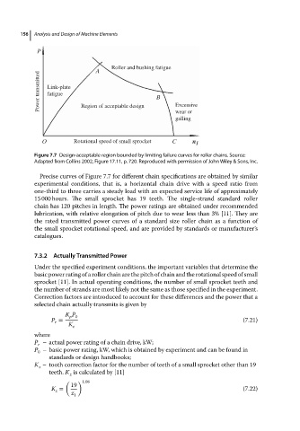
Roller and bushing fatigue
A
Power transmitted Link-plate B
fatigue
Excessive
Region of acceptable design
wear or
galling
O Rotational speed of small sprocket C n 1
Figure 7.7 Design-acceptable region bounded by limiting failure curves for roller chains. Source:
Adapted from Collins 2002, Figure 17.11, p. 720. Reproduced with permission of John Wiley & Sons, Inc.
Precise curves of Figure 7.7 for different chain specifications are obtained by similar
experimental conditions, that is, a horizontal chain drive with a speed ratio from
one-third to three carries a steady load with an expected service life of approximately
15 000 hours. The small sprocket has 19 teeth. The single-strand standard roller
chain has 120 pitches in length. The power ratings are obtained under recommended
lubrication, with relative elongation of pitch due to wear less than 3% [11]. They are
the rated transmitted power curves of a standard size roller chain as a function of
the small sprocket rotational speed, and are provided by standards or manufacturer’s
catalogues.
7.3.2 Actually Transmitted Power
Under the specified experiment conditions, the important variables that determine the
basic power rating of a roller chain are the pitch of chain and the rotational speed of small
sprocket [11]. In actual operating conditions, the number of small sprocket teeth and
the number of strands are most likely not the same as those specified in the experiment.
Correction factors are introduced to account for these differences and the power that a
selected chain actually transmits is given by
K P
p 0
P = (7.21)
r
K z
where
P – actual power rating of a chain drive, kW;
r
P – basic power rating, kW, which is obtained by experiment and can be found in
0
standards or design handbooks;
K – tooth correction factor for the number of teeth of a small sprocket other than 19
z
teeth. K is calculated by [11]
z
( ) 1.08
19
K = (7.22)
z
z 1