
Page 173 - Analysis and Design of Machine Elements
P. 173
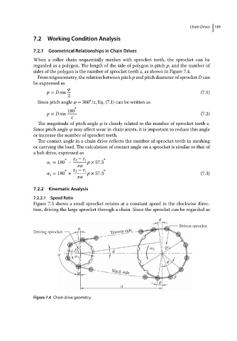
7.2 Working Condition Analysis                                  Chain Drives  151
                          7.2.1  Geometrical Relationships in Chain Drives
                          When a roller chain sequentially meshes with sprocket teeth, the sprocket can be
                          regarded as a polygon. The length of the side of polygon is pitch p,and thenumberof
                          sides of the polygon is the number of sprocket teeth z, as shown in Figure 7.4.
                            From trigonometry, the relation between pitch p and pitch diameter of sprocket D can
                          be expressed as

                               p = D sin                                                      (7.1)
                                        2
                                                 ∘
                            Since pitch angle    = 360 /z, Eq. (7.1) can be written as
                                           ∘
                                        180
                               p = D sin                                                      (7.2)
                                         z
                            The magnitude of pitch angle    is closely related to the number of sprocket teeth z.
                          Since pitch angle    may affect wear in chain joints, it is important to reduce this angle
                          or increase the number of sprocket teeth.
                            The contact angle in a chain drive reflects the number of sprocket teeth in meshing
                          or carrying the load. The calculation of contact angle on a sprocket is similar to that of
                          abeltdrive,expressed as
                                       ∘  z − z 1     ∘
                                           2
                                  = 180 −       p × 57.3
                                1
                                              a
                                       ∘  z − z 1     ∘
                                           2
                                  = 180 +       p × 57.3                                      (7.3)
                                2
                                              a
                          7.2.2  Kinematic Analysis
                          7.2.2.1  Speed Ratio
                          Figure 7.5 shows a small sprocket rotates at a constant speed in the clockwise direc-
                          tion, driving the large sprocket through a chain. Since the sprocket can be regarded as

                                                                             θ
                                            θ                                        Driven sprocket
                          Driving sprocket               Tension side


                                                                         ω 2    D 2
                                           D 1            θ
                                    α
                                           ω 1
                                                                                φ
                                            θ             Slack side
                                                                                   p
                                                                             θ
                                                             a

                          Figure 7.4 Chain drive geometry.