
Page 174 - Analysis and Design of Machine Elements
P. 174
Analysis and Design of Machine Elements
152
vʹ = R 1 ω 1 sinβ
v
γ γ
R 1 ω 1
β
v/cosγ = R 2 ω 2
β v = R 1 ω 1 cosβ
D 2
D 1
O 2 ω 1
O 1
ω 2
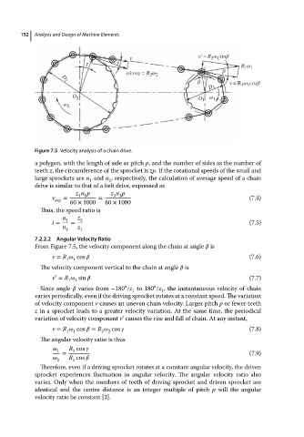
Figure 7.5 Velocity analysis of a chain drive.
a polygon, with the length of side as pitch p,and thenumberofsidesasthe number of
teeth z, the circumference of the sprocket is zp.Ifthe rotational speedsofthe smalland
large sprockets are n and n , respectively, the calculation of average speed of a chain
1 2
drive is similar to that of a belt drive, expressed as
z n p z n p
2 2
1 1
v avg = = (7.4)
60 × 1000 60 × 1000
Thus, the speed ratio is
n 1 z 2
i = = (7.5)
n 2 z 1
7.2.2.2 Angular Velocity Ratio
From Figure 7.5, the velocity component along the chain at angle is
v = R cos (7.6)
1
1
The velocity component vertical to the chain at angle is
′
v = R sin (7.7)
1 1
∘ ∘
Since angle varies from −180 /z to 180 /z , the instantaneous velocity of chain
1
1
varies periodically, even if the driving sprocket rotates at a constant speed. The variation
of velocity component v causes an uneven chain velocity. Larger pitch p or fewer teeth
z in a sprocket leads to a greater velocity variation. At the same time, the periodical
variation of velocity component v’ causes the rise and fall of chain. At any instant,
v = R cos = R cos (7.8)
1
1
2
2
The angular velocity ratio is thus
1 R cos
2
= (7.9)
R cos
2 1
Therefore, even if a driving sprocket rotates at a constant angular velocity, the driven
sprocket experiences fluctuation in angular velocity. The angular velocity ratio also
varies. Only when the numbers of teeth of driving sprocket and driven sprocket are
identical and the centre distance is an integer multiple of pitch p will the angular
velocity ratio be constant [2].