Page 264 - Analysis and Design of Machine Elements
P. 264

Analysis and Design of Machine Elements
                   242
                       9.3 Load Carrying Capacities
                       The determination of load carrying capacity for wormgear drives is more complicated
                       than for other types of gear drives due to complex profile geometry. Besides, wor-
                       mgear drive capacity is often limited not only by fatigue strength but also by thermal
                       capacity.
                         However, since an Archimedean wormgear drive resembles the meshing of helical
                       gear and rack in the central plane, it is reasonable to predict contact and bending fatigue
                       strength similar to those for helical gears, with factors introduced to account for their
                       differences.

                       9.3.1  Tooth Surface Fatigue Strength Analysis

                       Usually, hardened steel worms operate with soft bronze wormgears. As worm threads
                       are inherently strong and robust, the surface fatigue strength analysis is only performed
                       on wormgear teeth.
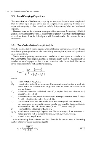
                         Similar to other gearings, contact stress calculation on wormgears is carried out on
                       the basis that the stress at pitch point does not vary greatly from the maximum stress
                       at other points of engagement, but is more convenient to be determined. The contact
                       stress calculation starts with the Hertz formula,
                                    √
                                    √        (  1  1  )
                                    √            ±
                                    √  KF
                                    √    n  •     1     2
                              Hmax  = √     (   2     2  )
                                        L     1−    1−  
                                                1  +  2
                                               E 1  E 2
                       where
                       K      –loadfactor, K = K K K ;
                                              A      v
                       K      – application factor. Since wormgear drives operate smoothly, low to moderate
                         A
                              values within the recommended range from Table 2.1 can be selected for worm
                              gearing design;
                       K      – face load factor. For stable load, select K = 1.0; For shock and vibration load,
                                                                   
                              select K = 1.1–1.3 [6];
                                      
                                                                                       −1
                       K      – dynamic factor. For pitch line velocity of a wormgear less than 3 m s ,select
                         v
                              K = l.0–1.1; otherwise, select K = 1.1–l.2;
                               v                        v
                       Z      – elastic coefficient. For hardened steel worms mating with cast tin bronze,
                         E
                              cast aluminium bronze, cast irons and nodular cast iron, the elastic coefficients
                                                                    −2 1/2
                              are selected as 155, 156, 162 and 181.4 (N mm ) , respectively [6].
                       F      – normal force, calculated by Eq. (9.13);
                         n
                          ,     – radius of curvature at pitch point, mm; Since a wormgear drive resembles a
                        1  2
                              helical gear and rack at the central plane,    =∞,    ≈ d sin  /2cos  .
                                                                 1
                                                                            2
                                                                        2
                       L      – total contact length, mm.
                         After substituting these variables into Hertz formula, the contact stress at the mating
                       surface of the wormgear is estimated as [6]
                                    √
                                      9.4KT 2
                                = Z E     2  ≤ [   ]                                      (9.15)
                                                 H
                              H
                                       d d
                                        1 2
   259   260   261   262   263   264   265   266   267   268   269