
Page 261 - Analysis and Design of Machine Elements
P. 261
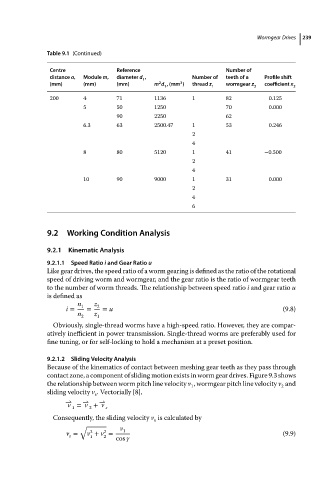
Table 9.1 (Continued)                                        Wormgear Drives  239
                           Centre             Reference                      Number of
                           distance a,  Module m,  diameter d ,     Number of  teeth of a  Profile shift
                                                     1
                                                          2
                                                                3
                           (mm)     (mm)      (mm)       m d ,(mm )  thread z  wormgear z  coefficient x
                                                            1            1            2          2
                           200      4         71         1136       1        82           0.125
                                    5         50         1250                70           0.000
                                              90         2250                62
                                    6.3       63         2500.47    1        53           0.246
                                                                    2
                                                                    4
                                    8         80         5120       1        41          −0.500
                                                                    2
                                                                    4
                                    10        90         9000       1        31           0.000
                                                                    2
                                                                    4
                                                                    6


                          9.2 Working Condition Analysis

                          9.2.1  Kinematic Analysis

                          9.2.1.1  Speed Ratio i and Gear Ratio u
                          Like gear drives, the speed ratio of a worm gearing is defined as the ratio of the rotational
                          speed of driving worm and wormgear, and the gear ratio is the ratio of wormgear teeth
                          to the number of worm threads. The relationship between speed ratio i and gear ratio u
                          is defined as
                                   n 1  z 2
                               i =   =    = u                                                 (9.8)
                                   n 2  z 1
                            Obviously, single-thread worms have a high-speed ratio. However, they are compar-
                          atively inefficient in power transmission. Single-thread worms are preferably used for
                          fine tuning, or for self-locking to hold a mechanism at a preset position.

                          9.2.1.2  Sliding Velocity Analysis
                          Because of the kinematics of contact between meshing gear teeth as they pass through
                          contact zone, a component of sliding motion exists in worm gear drives. Figure 9.3 shows
                          the relationship between worm pitch line velocity v , wormgear pitch line velocity v and
                                                                   1                         2
                          sliding velocity v . Vectorially [8],
                                        s
                               − ⇀  − ⇀  − ⇀
                                v = v + v  s
                                 1
                                      2
                            Consequently, the sliding velocity v is calculated by
                                                         s
                                   √           v
                                      2
                                          2
                               v =   v + v =    1                                             (9.9)
                                s
                                          2
                                      1
cos 