
Page 258 - Analysis and Design of Machine Elements
P. 258
Analysis and Design of Machine Elements
236
γ
p a
θ
c d f1 d 1 d a1
α
p t
c a
d a2 d 2 d f2
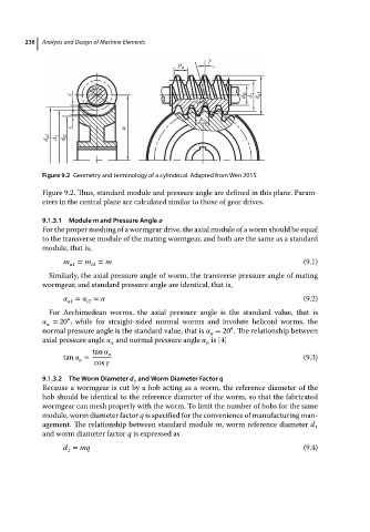
Figure 9.2 Geometry and terminology of a cylindrical. Adapted from Wen 2015.
Figure 9.2. Thus, standard module and pressure angle are defined in this plane. Param-
eters in the central plane are calculated similar to those of gear drives.
9.1.3.1 Module m and Pressure Angle a
For the proper meshing of a wormgear drive, the axial module of a worm should be equal
to the transverse module of the mating wormgear, and both are the same as a standard
module, that is,
m a1 = m = m (9.1)
t2
Similarly, the axial pressure angle of worm, the transverse pressure angle of mating
wormgear, and standard pressure angle are identical, that is,
a1 = = (9.2)
t2
For Archimedean worms, the axial pressure angle is the standard value, that is
∘
= 20 , while for straight-sided normal worms and involute helicoid worms, the
a
∘
normal pressure angle is the standard value, that is = 20 . The relationship between
n
axial pressure angle and normal pressure angle is [4]
a n
tan n
tan = (9.3)
a
cos
9.1.3.2 The Worm Diameter d and Worm Diameter Factor q
1
Because a wormgear is cut by a hob acting as a worm, the reference diameter of the
hob should be identical to the reference diameter of the worm, so that the fabricated
wormgear can mesh properly with the worm. To limit the number of hobs for the same
module, worm diameter factor q is specified for the convenience of manufacturing man-
agement. The relationship between standard module m, worm reference diameter d
1
and worm diameter factor q is expressed as
d = mq (9.4)
1