
Page 309 - Analysis and Design of Machine Elements
P. 309
Shafts
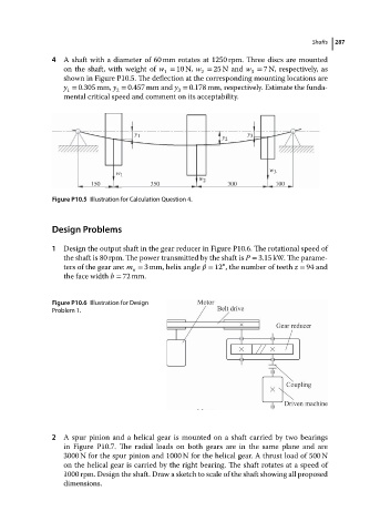
4 A shaft with a diameter of 60 mm rotates at 1250 rpm. Three discs are mounted 287
on the shaft, with weight of w = 10 N, w = 25 N and w = 7N, respectively, as
1
3
2
shown in Figure P10.5. The deflection at the corresponding mounting locations are
y = 0.305 mm, y = 0.457 mm and y = 0.178 mm, respectively. Estimate the funda-
1 2 3
mental critical speed and comment on its acceptability.
y 1 y 3
y 2
w
w 1 3
w 2
150 350 300 100
Figure P10.5 Illustration for Calculation Question 4.
Design Problems
1 Design the output shaft in the gear reducer in Figure P10.6. The rotational speed of
the shaft is 80 rpm. The power transmitted by the shaft is P = 3.15 kW. The parame-
∘
ters of the gear are: m = 3 mm, helix angle = 12 , the number of teeth z = 94 and
n
the face width b = 72 mm.
Figure P10.6 Illustration for Design
Problem 1.
2 A spur pinion and a helical gear is mounted on a shaft carried by two bearings
in Figure P10.7. The radial loads on both gears are in the same plane and are
3000 N for the spur pinion and 1000 N for the helical gear. A thrust load of 500 N
on the helical gear is carried by the right bearing. The shaft rotates at a speed of
1000 rpm. Design the shaft. Draw a sketch to scale of the shaft showing all proposed
dimensions.