
Page 310 - Analysis and Design of Machine Elements
P. 310
Analysis and Design of Machine Elements
288
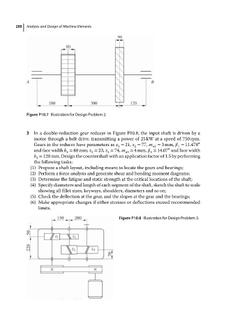
Figure P10.7 Illustration for Design Problem 2.
3 In a double-reduction gear reducer in Figure P10.8, the input shaft is driven by a
motor through a belt drive, transmitting a power of 25 kW at a speed of 750 rpm.
Gears in the reducer have parameters as z = 21, z = 77, m = 3mm, = 11.478 ∘
1 2 n1 1
∘
and face width b = 80 mm; z = 23, z = 74, m = 4mm, = 14.07 and face width
3
2
4
n3
3
b = 120 mm. Design the countershaft with an application factor of 1.5 by performing
4
the following tasks:
(1) Propose a shaft layout, including means to locate the gears and bearings;
(2) Perform a force analysis and generate shear and bending moment diagrams;
(3) Determine the fatigue and static strength at the critical locations of the shaft;
(4) Specify diameters and length of each segment of the shaft, sketch the shaft to scale
showing all fillet sizes, keyways, shoulders, diameters and so on;
(5) Check the deflection at the gear, and the slopes at the gear and the bearings;
(6) Make appropriate changes if either stresses or deflections exceed recommended
limits.
Figure P10.8 Illustration for Design Problem 3.