
Page 308 - Analysis and Design of Machine Elements
P. 308
Analysis and Design of Machine Elements
286
Calculation Questions
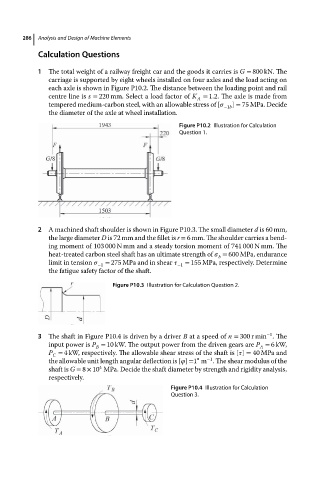
1 The totalweightofarailwayfreight carand thegoodsitcarries is G = 800 kN. The
carriage is supported by eight wheels installed on four axles and the load acting on
each axle is shown in Figure P10.2. The distance between the loading point and rail
centre line is s = 220 mm. Select a load factor of K = 1.2. The axle is made from
A
tempered medium-carbon steel, with an allowable stress of [ ] = 75 MPa. Decide
−1b
the diameter of the axle at wheel installation.
Figure P10.2 Illustration for Calculation
Question 1.
2 A machined shaft shoulder is shown in Figure P10.3. The small diameter d is 60 mm,
the large diameter D is 72 mm and the fillet is r = 6 mm. The shoulder carries a bend-
ing moment of 103 000 N mm and a steady torsion moment of 741 000 N mm. The
heat-treated carbon steel shaft has an ultimate strength of = 600 MPa, endurance
b
limit in tension −1 = 275 MPa and in shear −1 = 155 MPa, respectively. Determine
the fatigue safety factor of the shaft.
Figure P10.3 Illustration for Calculation Question 2.
−1
3 The shaft in Figure P10.4 is driven by a driver B at a speed of n = 300 r min .The
input power is P = 10 kW. The output power from the driven gears are P = 6kW,
A
B
P = 4 kW, respectively. The allowable shear stress of the shaft is [ ] = 40 MPa and
C
∘
−1
the allowable unit length angular deflection is [ ] =1 m . The shear modulus of the
4
shaft is G = 8 × 10 MPa. Decide the shaft diameter by strength and rigidity analysis,
respectively.
Figure P10.4 Illustration for Calculation
Question 3.