
Page 322 - Analysis and Design of Machine Elements
P. 322
Analysis and Design of Machine Elements
300
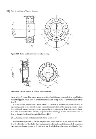
Figure 11.7 Radial load distribution in a radial bearing.
Figure 11.8 Force analysis of an angular contact bearing.
them is S = P tan . The vector summary of total radial components P is in equilibrium
i i i
with the applied radial load R. The sum of total axial component S is the induced thrust
i
load S.
In other words, the induced thrust load S is created by internal reaction force N in
i
the bearing. It is in the direction that forces the separation of the inner and outer rings.
To avoid such separation, these bearings usually work in pairs so that the induced thrust
load can be counteracted. That is, angular contact bearings should be installed face to
face or back to back, as illustrated in Figure 11.9.
(2) A bearing carries both radial load R and axial load A
As shown in Figure 11.8, the bearing carries a radial load R createsaninduced thrust
load S, which forces the shaft, the inner ring and rolling elements to move left, assuming
they move a short distance to the left and are finally balanced with an axial load A (not