
Page 323 - Analysis and Design of Machine Elements
P. 323
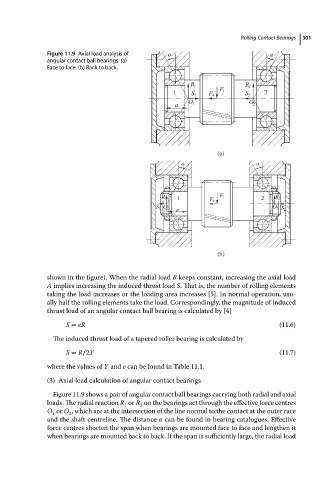
Figure 11.9 Axial load analysis of                      Rolling Contact Bearings  301
                          angular contact ball bearings. (a)
                          Face to face. (b) Back to back.


                                                                           (a)


                                                                           (b)


                          shown in the figure). When the radial load R keeps constant, increasing the axial load
                          A implies increasing the induced thrust load S. That is, the number of rolling elements
                          taking the load increases or the loading area increases [5]. In normal operation, usu-
                          ally half the rolling elements take the load. Correspondingly, the magnitude of induced
                          thrust load of an angular contact ball bearing is calculated by [4]
                               S = eR                                                        (11.6)

                            The induced thrust load of a tapered roller bearing is calculated by

                               S = R∕2Y                                                      (11.7)
                          where the values of Y and e canbefoundinTable 11.1.
                          (3) Axial load calculation of angular contact bearings

                            Figure 11.9 shows a pair of angular contact ball bearings carrying both radial and axial
                          loads. The radial reaction R or R on the bearings act through the effective force centres
                                                     2
                                                1
                          O or O ,which areatthe intersection of thelinenormaltothe contactatthe outer race
                           1
                                2
                          and the shaft centreline. The distance a canbefoundinbearing catalogues.Effective
                          force centres shorten the span when bearings are mounted face to face and lengthen it
                          when bearings are mounted back to back. If the span is sufficiently large, the radial load