
Page 324 - Analysis and Design of Machine Elements
P. 324
Analysis and Design of Machine Elements
302
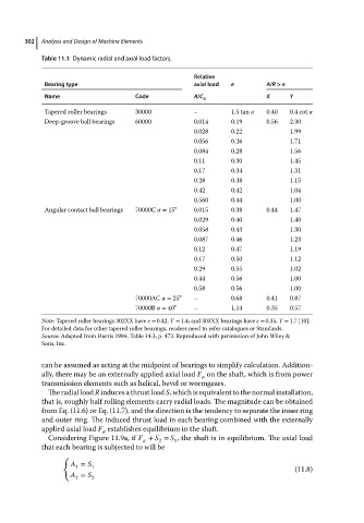
Table 11.1 Dynamic radial and axial load factors.
Relative
Bearing type axial load e A/R > e
Name Code A/C 0 X Y
Tapered roller bearings 30000 – 1.5 tan 0.40 0.4 cot
Deep-groove ball bearings 60000 0.014 0.19 0.56 2.30
0.028 0.22 1.99
0.056 0.26 1.71
0.084 0.28 1.56
0.11 0.30 1.45
0.17 0.34 1.31
0.28 0.38 1.15
0.42 0.42 1.04
0.560 0.44 1.00
Angular contact ball bearings 70000C = 15 ∘ 0.015 0.38 0.44 1.47
0.029 0.40 1.40
0.058 0.43 1.30
0.087 0.46 1.23
0.12 0.47 1.19
0.17 0.50 1.12
0.29 0.55 1.02
0.44 0.56 1.00
0.58 0.56 1.00
70000AC = 25 ∘ – 0.68 0.41 0.87
70000B = 40 ∘ – 1.14 0.35 0.57
Note: Tapered roller bearings 302XX have e = 0.42, Y = 1.4; and 303XX bearings have e = 0.35, Y = 1.7 [10].
For detailed data for other tapered roller bearings, readers need to refer catalogues or Standards.
Source: Adapted from Harris 1984, Table 14.3, p. 472. Reproduced with permission of John Wiley &
Sons, Inc.
can be assumed as acting at the midpoint of bearings to simplify calculation. Addition-
ally, there may be an externally applied axial load F on the shaft, which is from power
a
transmission elements such as helical, bevel or wormgears.
The radial load R induces a thrust load S, which is equivalent to the normal installation,
that is, roughly half rolling elements carry radial loads. The magnitude can be obtained
from Eq. (11.6) or Eq. (11.7), and the direction is the tendency to separate the inner ring
and outer ring. The induced thrust load in each bearing combined with the externally
applied axial load F establishes equilibrium in the shaft.
a
Considering Figure 11.9a, if F + S = S , the shaft is in equilibrium. The axial load
a 2 1
that each bearing is subjected to will be
{
A = S 1
1
(11.8)
A = S
2 2