
Page 368 - Analysis and Design of Machine Elements
P. 368
Analysis and Design of Machine Elements
346
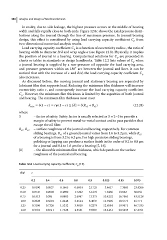
In reality, due to side leakage, the highest pressure occurs at the middle of bearing
width and falls rapidly close to both ends. Figure 12.8c shows the axial pressure distri-
butions along the journal through the line of maximum pressure. In journal bearing
design, this effect is considered by using load carrying capacity coefficient C from
p
two-dimensional numerical analysis results.
Load carrying capacity coefficient C is a function of eccentricity radio , the ratio of
p
bearing width to diameter B/d and wrap angle (see Figure 12.8). Physically, it implies
the position of journal in a bearing. Computerized solutions for C are presented in
p
charts or tables in standards or design handbooks. Table 12.2 lists values of C when
p
a journal bearing is supplied by a non-pressure oil opposite the load carrying area,
∘
and pressure generates within an 180 arc between the journal and liner. It can be
noticed that with the increase of and B/d, the load carrying capacity coefficient C p
also increases.
As discussed before, the moving journal and stationary bearing are separated by
lubricant film that supports load. Reducing the minimum film thickness will increase
eccentricity ratio , and consequently increase the load carrying capacity coefficient
C . However, the minimum film thickness is limited by the asperities of both journal
p
and bearing. The minimum film thickness must meet
h min = (1 − )= r (1 − ) ≥ [h]= S(R + R ) (12.24)
z1
z2
where
S – factor of safety. Safety factor is usually selected as S = 2∼3 to provide a
margin of safety to prevent metal-to-metal contact and to pass particles that
escape the oil filter.
R , R – surface roughness of the journal and bearing, respectively. For common
z1 z2
sliding bearings, R of a ground journal varies from 1.6 to 3.2 μm, while R
z1 z2
of a bearing is from 3.2 to 6.3 μm. For high precision sliding bearings,
polishing or lapping can produce a surface finish in the order of 0.2 to 0.8 μm
for a journal and 0.4 to 1.6 μm for a bearing [5, 16].
[h] – the allowable minimum film thickness, which depends on the surface
roughness of the journal and bearing.
Table 12.2 Load carrying capacity coefficient, C [15].
p
B/d
0.2 0.4 0.6 0.8 0.9 0.925 0.95 0.975
0.25 0.0190 0.0537 0.1465 0.6054 2.1725 3.4617 7.3485 23.4266
0.50 0.0747 0.2002 0.4900 1.7222 5.1676 7.8436 13.852 38.055
0.75 0.1513 0.381 0.8883 2.6987 7.1375 10.4252 16.7465 43.5128
1.00 0.2328 0.5601 1.2448 3.4514 8.4037 11.9405 18.5775 45.771
1.25 0.3106 0.7326 1.5312 3.9818 9.2279 12.8584 19.9471 46.7535
1.50 0.3781 0.8711 1.7528 4.3531 9.6987 13.4451 20.5259 47.2761