
Page 388 - Analysis and Design of Machine Elements
P. 388
Analysis and Design of Machine Elements
366
T f friction torque, N mm y axial misalignment, or parallel
[T] rated torque of a coupling or clutch, offset, mm
Nmm z number of contact surfaces
x end float, mm angular misalignment, ∘
13.1 Introduction to Couplings
13.1.1 Applications, Characteristics and Structures
A coupling is a device used to connect two shafts end to end to transmit power and
torque. The output shaft of a driver, such as a motor or engine, is connected to the input
shaft of a transmission, or a driven machine through a coupling (Figure 6.1) [1]. Since
power units, transmission units and driven machines are often manufactured separately,
couplings are indispensable in mechanical power transmission system. They are widely
used in machines in automotive, petroleum, chemical, gas, electric power and steel and
other industries.
Apart from the primary function of connecting shafts to transmit power and torque,
couplings can compensate for misalignments between the coupled shafts. Some cou-
plings can also absorb shock and vibration, or act as a safety device to prevent overload
on a machine. The shafts connected by couplings normally do not allow disconnection
during operation. However, during repair, couplings facilitate temporary disconnection
for safety concern.
Couplings differ widely in size, appearance and characteristics. Nevertheless, all cou-
plings consist of three basic parts, that is, two shaft hubs and a connecting element. Most
of couplings are highly standardized and commercially available from manufacturers.
Couplings can be either selected or designed according to application requirements.
13.1.2 Shaft Misalignments
Although precise alignment is desirable for all machines, perfect alignment is difficult
during initial assembly and installation, and almost impossible to achieve and maintain
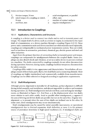
during operation [2]. Shaft misalignments include end float, axial and angular misalign-
ments, as illustrated in Figure 13.1. End float, x, is the displacement when two shafts
move relative to each other axially. Axial or parallel offset misalignment, y,appears if
the axes of driving and driven shafts are parallel, but not on the same line. Angular mis-
alignment, ,ispresent when theaxesoftwo shafts areinclinedone to theother.In
some cases, these misalignments may occur simultaneously.
Shaft misalignments may be caused by initial assembly inaccuracies, or operational
misalignments due to thermal expansion, shaft deflection or wear. It is the primary
source of premature downtime in high-speed machinery [2]. If misaligned shafts are
(a) End float, x (b) Axial misalignment, y (c) Angular misalignment, α
Figure 13.1 Shaft misalignments.