
Page 390 - Analysis and Design of Machine Elements
P. 390
Analysis and Design of Machine Elements
368
(a) (b)
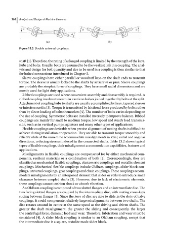
Figure 13.2 Double universal couplings.
shaft [1]. Therefore, the rating of a flanged coupling is limited by the strength of the keys,
hubs and bolts. Usually, bolts are assumed to be the weakest link in a coupling. The anal-
ysis and design for bolt quantity and size to be used in a coupling is then similar to that
for bolted connections introduced in Chapter 3.
Sleeve couplings have either parallel or woodruff keys on the shaft ends to transmit
torque. The sleeve is usually locked to the shafts by setscrews or pins. Sleeve couplings
are probably the simplest form of couplings. They have small radial dimensions and are
mostly used for light duty applications.
Ribbed couplings are used where convenient assembly and disassembly is required. A
ribbed coupling involves two similar cast iron halves joined together by bolts at the split.
Attachment of coupling hubs to shafts are usually accomplished by keys, tapered sleeves
or interference fits [3]. Torque is transmitted by frictional force produced by bolts rather
than by direct loading of bolts themselves [4]. The number of bolts varies depending on
the size of coupling. Symmetric bolts are installed inversely to improve balance. Ribbed
couplings are mainly for small to medium torque, low speed and steady load transmis-
sion, such as in vertical pumps, agitators and many other types of applications.
Flexible couplings are desirable when precise alignment of mating shafts is difficult to
achieve during installation or operation. They are able to transmit torque smoothly and
reliably while at the same time accommodate misalignments in axial, radial and angular
directions, reducing stresses induced in the connected shafts. Table 13.2 shows typical
types of flexible couplings, their misalignment accommodation capabilities, features and
applications.
Misalignments in flexible couplings are compensated for by either mechanical com-
ponents, resilient materials or a combination of both [2]. Correspondingly, they are
classified as mechanical flexible couplings, elastomeric couplings and metallic element
couplings. Mechanical flexible couplings include Oldham couplings, slider block cou-
plings, universal couplings, gear couplings and chain couplings. These couplings accom-
modate misalignments by an interposed element that slides or rolls to introduce small
clearance between coupled shafts [3]. However, due to lack of elastomeric elements,
these couplings cannot cushion shock or absorb vibration.
An Oldham coupling is composed of two slotted flanges and an intermediate disc. The
two facing slotted flanges are coupled by the intermediate disc, with mating cross-keys
sliding between flanges [3]. Since the keys of disc are able to slide in the slots of halve
couplings, it could compensate relatively large misalignments between two shafts. The
disc rotatesaroundits centre at thesamespeed as thedriving anddrivenshafts. The
greater the shaft misalignment, the greater the sliding and consequently, the larger
the centrifugal force, dynamic load and wear. Therefore, lubrication and wear must be
considered [4]. A slider block coupling is similar to an Oldham coupling, except that
the intermediate disc is a square, textolite made slider block.