
Page 425 - Analysis and Design of Machine Elements
P. 425
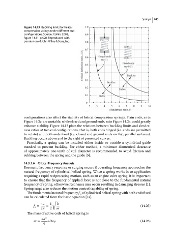
Figure 14.13 Buckling limits for helical                           Springs  403
                          compression springs under different end
                          configurations. Source: Collins 2002,
                          figure 14.11, p 528. Reproduced with
                          permission of John Wiley & Sons, Inc.


                          configurations also affect the stability of helical compression springs. Plain ends, as in
                          Figure 14.2c, are unstable, while closed and ground ends, as in Figure 14.2a, could greatly
                          enhance stability. Figure 14.13 plots the relations between buckling limits and slender-
                          ness ratios at two end configurations, that is, both ends hinged (i.e. ends are permitted
                          to rotate) and both ends fixed (i.e. closed and ground ends on flat, parallel surfaces).
                          Buckling occurs above and to the right of presented curves.
                            Practically, a spring can be installed either inside or outside a cylindrical guide
                          mandrel to prevent buckling. For either method, a minimum diametrical clearance
                          of approximately one-tenth of coil diameter is recommended to avoid friction and
                          rubbing between the spring and the guide [5].

                          14.3.1.6  Critical Frequency Analysis
                          Resonant frequency response or surging occurs if operating frequency approaches the
                          natural frequency of cylindrical helical spring. When a spring works in an application
                          requiring a rapid reciprocating motion, such as an engine valve spring, it is important
                          to ensure that the frequency of applied force is not close to the fundamental natural
                          frequency of spring, otherwise resonance may occur resulting in damaging stresses [1].
                          Spring surge also reduces the motion control capability of spring.
                            The fundamental natural frequency f of cylindrical helical spring with both ends fixed
                                                          n
                          can be calculated from the basic equation [14],
                                          √
                                       n  1  k
                               f =     =                                                    (14.25)
                                n
                                   2     2  m
                            The mass of active coils of helical spring is
                                      d 2
                               m =       Dn                                                 (14.26)
                                     4