
Page 427 - Analysis and Design of Machine Elements
P. 427
14.3.3 Analysis of Helical Torsion Springs Springs 405
14.3.3.1 Load-Deflection Relationship
Like extension and compression springs, torsion springs also work properly within the
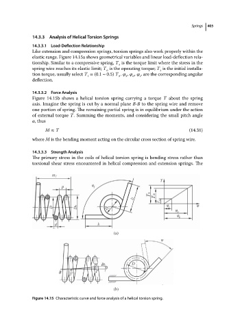
elastic range. Figure 14.15a shows geometrical variables and linear load-deflection rela-
tionship. Similar to a compressive spring, T is the torque limit where the stress in the
s
spring wire reaches its elastic limit; T is the operating torque; T is the initial installa-
i
o
tion torque, usually select T = (0.1 ∼ 0.5) T . , , , are the corresponding angular
i
i
s
o
o
deflection.
14.3.3.2 Force Analysis
Figure 14.15b shows a helical torsion spring carrying a torque T about the spring
axis. Imagine the spring is cut by a normal plane B-B to the spring wire and remove
one portion of spring. The remaining partial spring is in equilibrium under the action
of external torque T. Summing the moments, and considering the small pitch angle
,thus
M ≈ T (14.31)
where M is the bending moment acting on the circular cross section of spring wire.
14.3.3.3 Strength Analysis
The primary stress in the coils of helical torsion spring is bending stress rather than
torsional shear stress encountered in helical compression and extension springs. The
(a)
(b)
Figure 14.15 Characteristic curve and force analysis of a helical torsion spring.