
Page 432 - Analysis and Design of Machine Elements
P. 432
Analysis and Design of Machine Elements
410
While for ordinary extension springs or compression springs,
Gd
n = max ≥ 3
8F C 3
max
Normally, the recommended number of active coils should be within the range of
3–15. The total number of coils should account for end coil configurations, which
can be found in Table 14.1. This influences overall spring flexibility.
5) Check rigidity, load, deflection, static and fatigue strength, stability of compression
spring and potential surging if required
6) Decide the dimension of springs
For a compression spring, closed and ground ends are usually a good choice; while for
an extension spring, a full end loop over the centre is preferred. A clearance between
coils should be allowed to avoid coil-to-coil contact when a spring is at its maxi-
1
mum operating deflection. After calculation, it is required to check whether spring
variables satisfy installation requirements.
7) Produce working drawing for the spring
14.4.5 Design Cases
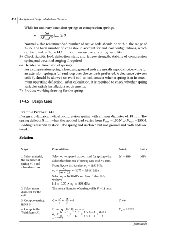
Example Problem 14.1
Design a cylindrical helical compression spring with a mean diameter of 18 mm. The
spring deflects 5 mm when the applied load varies from F = 150 N to F = 250 N.
min max
Loading is essentially static. The spring end is closed but not ground and both ends are
fixed.
Solution
Steps Computation Results Units
1. Select material, Select oil tempered carbon steel for spring wire. [ ] = 880 MPa
the diameter of Select the diameter of spring wire as d = 3 mm.
spring wire and From Figure 14.16, select = 1150 MPa,
allowable stress e
= e =(1277 ∼ 1916) MPa
b
0.6 ∼ 0.9
Select = 1600 MPa and from Table 14.3,
b
we have
[ ]=0.55 × = 880 MPa
b
2. Select mean The mean diameter of spring coil is D = 18 mm.
diameter for the
coil
D 18
3. Compute spring C = = = 6 C = 6
index C d 3
4. Compute the From Eq. (14.11), we have K = 1.2525
w
Wahl factor K 4C − 1 0.615 4 × 6 − 1 0.615
w K ≈ + = +
w
4C − 4 C 4 × 6 − 4 6
= 1.2525
(continued)