Page 435 - Analysis and Design of Machine Elements
P. 435
Steps Computation Results Springs 413
Units
From
Table 14.2, select G = 80 000 MPa. From
Eq. (14.23)
Gd Gd 4 80000 × 3 4
n = = = = 10.42
8C k 8D k 8 × 18 × 13.33
3
3
3
Select n = 11, and the stiffness of the designed
spring is:
Gd 4 80000 × 3 4 k = 12.63 N
k = = = 12.63 N∕mm mm −1
3
8D n 8 × 18 × 11
3
Close to the required spring rate.
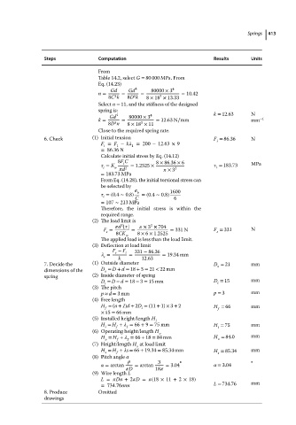
6. Check (1) Initial tension F = 86.36 N
i
F = F − k = 200 − 12.63 × 9
i 1 1
=86.36 N
Calculate initial stress by Eq. (14.12)
8F C 8 × 86.36 × 6
i
= K w d 2 = 1.2525 × × 3 2 = 183.73 MPa
i
i
= 183.73 MPa
From Eq. (14.28), the initial torsional stress can
be selected by
b 1600
=(0.4 ∼ 0.8) C =(0.4 ∼ 0.8) 6
i
= 107 ∼ 213 MPa
Therefore, the initial stress is within the
required range.
(2) The load limit is
2
2
d [ ] × 3 × 704
F = = = 331 N F = 331 N
s
s
8CK w 8 × 6 × 1.2525
The applied load is less than the load limit.
(3) Deflection at load limit
F − F 331 − 86.36
= s i = = 19.34 mm
s k 12.63
7. Decide the (1) Outside diameter D = 21 mm
o
dimensions of the D = D + d = 18 + 3 = 21 < 22 mm
o
spring (2) Inside diameter of spring
D = D − d = 18 − 3 = 15 mm D = 15 mm
i
i
(3) The pitch
p ≈ d = 3mm p = 3 mm
(4) Free length
H = (n + 1)d + 2D = (11 + 1) × 3 + 2 H = 66 mm
i
f
f
× 15 = 66 mm
(5) Installed height/length H
i
H = H + = 66 + 9 = 75 mm H = 75 mm
i f 1 i
(6) Operating height/length H o
H = H + = 66 + 18 = 84 mm H = 84.0 mm
o
o
2
f
(7) Height/length H at load limit
s
H = H + s = 66 + 19.34 = 85.34 mm H = 85.34 mm
f
s
s
(8) Pitch angle
p 3 ∘ ∘
= arctan = arctan = 3.04 = 3.04
D 18
(9) Wire length L
L = Dn +2 D = (18 × 11 + 2 × 18)
= 734.76mm L = 734.76 mm
8. Produce Omitted
drawings

