
Page 433 - Analysis and Design of Machine Elements
P. 433
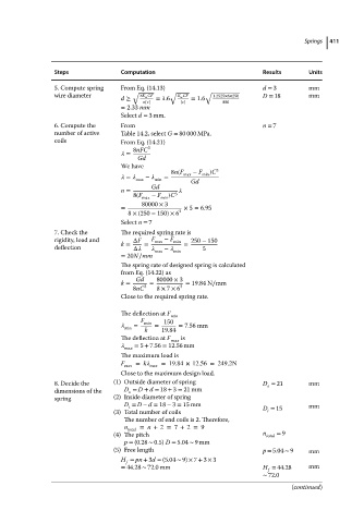
Steps            Computation                           Results    Springs  411
                                                                                              Units
                           5. Compute spring  From Eq. (14.13)                    d = 3       mm
                           wire diameter       √  8K w CF  √  K w CF  √  1.2525×6×250  D = 18  mm
                                            d ≥       = 1.6    = 1.6
                                                    [  ]    [  ]       880
                                            = 2.33 mm
                                            Select d = 3 mm.
                           6. Compute the   From                                  n = 7
                           number of active  Table 14.2, select G = 80 000 MPa.
                           coils            From Eq. (14.21)
                                                8nFC  3
                                               =
                                                 Gd
                                            We have
                                                          8n(F  − F  )C 3
                                               =     −     =  max  min
                                                max  min       Gd
                                                    Gd
                                            n =
                                                8(F  − F  )C 3
                                                  max  min
                                                  80000 × 3
                                            =                × 5 = 6.95
                                              8 ×(250 − 150)× 6 3
                                            Select n = 7
                           7. Check the     The required spring rate is
                           rigidity, load and   ΔF  F max  − F min  250 − 150
                           deflection        k =  Δ    =     max  −    min  =  5
                                            = 20N∕mm

                                            The spring rate of designed spring is calculated
                                            from Eq. (14.22) as
                                                Gd    80000 × 3
                                            k =     =        = 19.84 N∕mm
                                                8nC  3  8 × 7 × 6 3
                                            Close to the required spring rate.
                                            The deflection at F  min
                                                  F     150
                                                =  min  =   = 7.56 mm
                                             min   k   19.84
                                            The deflection at F  max  is
                                               max  = 5 + 7.56 = 12.56 mm
                                            The maximum load is
                                            F   = k    =19.84 × 12.56 = 249.2N
                                             max    max
                                            Close to the maximum design load.
                           8. Decide the  (1) Outside diameter of spring          D = 21      mm
                                                                                   o
                           dimensions of the  D = D + d = 18 + 3 = 21 mm
                                              o
                           spring         (2) Inside diameter of spring
                                             D = D − d = 18 − 3 = 15 mm                       mm
                                              i
                                                                                   i
                                          (3) Total number of coils               D = 15
                                             The number of end coils is 2. Therefore,
                                             n total  = n +2 = 7 +2 = 9
                                          (4) The pitch                           n total  = 9
                                             p = (0.28 ∼ 0.5) D = 5.04 ∼ 9mm
                                          (5) Free length                         p = 5.04 ∼ 9  mm
                                            H = pn + 3d = (5.04 ∼ 9) × 7 + 3 × 3
                                              f
                                            = 44.28 ∼ 72.0 mm                     H = 44.28   mm
                                                                                   f
                                                                                  ∼ 72.0
                                                                                          (continued)