
Page 55 - Analysis and Design of Machine Elements
P. 55
Strength of Machine Elements
final fracture zone is the sudden fracture area [10]. Figure 2.3b shows fracture surface 33
diagram due to static fracture for comparison.
The crack initiation and propagation are affected by several conditions. Apart from
localized stresses and material microstructures, other factors include tensile residual
stresses, temperature, environment and cycling frequency of loads. The estimation of
fatigue behaviour requires consideration of these factors, with emphasis on geometries,
materials and loading conditions.
2.3.2 Stress-Life Diagrams
The fatigue strength represents a material’s capability of withstanding fluctuating loads,
which is obtained from a standard fatigue test. In the test, a regular cyclic load with a
stress ratio of either −1 or 0 is applied to a smooth or notched specimen on a fatigue
testing machine. Different magnitudes of load are applied to generate different stress
levels. The number of cycles to failure or fatigue life, corresponding to different stress
levels, is recorded. The stress-life diagram (also known as -N or S-N curve), which
depicts stress versus the number of cycles to failure, is developed as shown in Figure 2.4.
From this figure, the fatigue strength of materials can be determined.
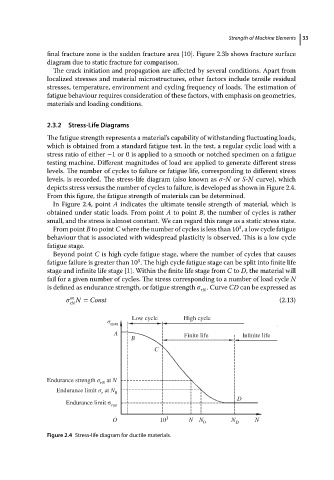
In Figure 2.4, point A indicates the ultimate tensile strength of material, which is
obtained under static loads. From point A to point B, the number of cycles is rather
small, and the stress is almost constant. We can regard this range as a static stress state.
3
From point B to point C where the number of cycles is less than 10 , a low cycle fatigue
behaviour that is associated with widespread plasticity is observed. This is a low cycle
fatigue stage.
Beyond point C is high cycle fatigue stage, where the number of cycles that causes
3
fatigue failure is greater than 10 . The high cycle fatigue stage can be split into finite life
stage and infinite life stage [1]. Within the finite life stage from C to D, the material will
fail for a given number of cycles. The stress corresponding to a number of load cycle N
is defined as endurance strength, or fatigue strength .Curve CD canbeexpressed as
rN
m
N = Const (2.13)
rN
σ Low cycle High cycle
max
A Finite life Infinite life
B
C
Endurance strength σ at N
rN
Endurance limit σ at N
r 0
D
Endurance limit σ
r∞
O 10 3 N N N N
0 D
Figure 2.4 Stress-life diagram for ductile materials.