Page 57 - Analysis and Design of Machine Elements
P. 57

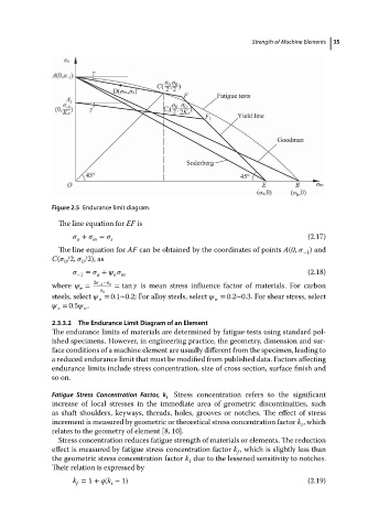
Figure 2.5 Endurance limit diagram.                 Strength of Machine Elements  35

                            The line equation for EF is
                                  +    =    s                                                (2.17)
                                     m
                                a
                            The line equation for AF can be obtained by the coordinates of points A(0,    )and
                                                                                            −1
                          C(   /2,    /2), as
                             0    0
                                   =    +                                                    (2.18)
                                −1    a      m
                          where    =  2   −1 −   0  = tan    is mean stress influence factor of materials. For carbon
                                   
                                          0
                          steels, select    = 0.1∼0.2; For alloy steels, select    = 0.2∼0.3. For shear stress, select
                                                                       
                             = 0.5   .
                             
                                    
                          2.3.3.2  The Endurance Limit Diagram of an Element
                          The endurance limits of materials are determined by fatigue tests using standard pol-
                          ished specimens. However, in engineering practice, the geometry, dimension and sur-
                          face conditions of a machine element are usually different from the specimen, leading to
                          a reduced endurance limit that must be modified from published data. Factors affecting
                          endurance limits include stress concentration, size of cross section, surface finish and
                          so on.

                          Fatigue Stress Concentration Factor, k  Stress concentration refers to the significant
                                                        f
                          increase of local stresses in the immediate area of geometric discontinuities, such
                          as shaft shoulders, keyways, threads, holes, grooves or notches. The effect of stress
                          increment is measured by geometric or theoretical stress concentration factor k ,which
                                                                                           t
                          relates to the geometry of element [8, 10].
                            Stress concentration reduces fatigue strength of materials or elements. The reduction
                          effect is measured by fatigue stress concentration factor k , which is slightly less than
                                                                          f
                          the geometric stress concentration factor k due to the lessened sensitivity to notches.
                                                              t
                          Their relation is expressed by
                               k = 1 + q(k − 1)                                              (2.19)
                                f
                                         t
   52   53   54   55   56   57   58   59   60   61   62