
Page 62 - Analysis and Design of Machine Elements
P. 62
Analysis and Design of Machine Elements
40
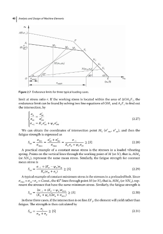
Figure 2.7 Endurance limits for three typical loading cases.
limit at stress ratio r. If the working stress is located within the area of ΔOA F ,the
1 1
endurance limit can be found by solving two line equations of OM and A F to find out
1
1 1
the intersection, by
′
⎧ a ae
⎪ = ′
⎨ m me (2.27)
′
⎪ = K + ′
−1 ae me
⎩
We can obtain the coordinates of intersection point M ( ′ me , ′ ae ), and then the
1
fatigue strength is expressed as
′
′
lim + me −1
ae
S = = = ≥ [S] (2.28)
ca
max max K +
a
m
A practical example of a constant mean stress is the stresses in a loaded vibrating
spring. Points on the vertical lines through the working point of M (or N), that is, MM
2
(or NN ), represent the same mean stress. Similarly, the fatigue strength for constant
2
mean stress is
−1 +(K − ) m
S = ≥ [S] (2.29)
ca
K ( + )
m
a
A typical example of constant minimum stress is the stresses in a preloaded bolt. Since
∘
= − = Const., the 45 lines through point M (or N), that is, MM (or NN ), rep-
min m a 3 3
resent the stresses that have the same minimum stress. Similarly, the fatigue strength is
2 −1 +(K − ) min
S = ≥ [S] (2.30)
ca
(K + )(2 + )
a min
In these three cases, if the intersection is on line EF , the element will yield rather than
1
fatigue. The strength is then calculated by
s
S = ≥ [S] (2.31)
ca
+ a
m