
Page 71 - Analysis and Design of Machine Elements
P. 71
Results
Steps Computation Strength of Machine Elements 49
Units
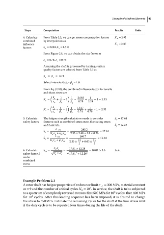
4. Calculate From Table 2.2, we can get stress concentration factors K = 2.95
combined by interpolation as
influence K = 2.33
factors k = 2.083, k = 1.517
From Figure 2.6, we can obtain the size factor as
= 0.78, = 0.74
Assuming the shaft is processed by turning, surface
quality factors are selected from Table 2.3 as,
= =0.78
Select intensity factor = 1.0.
q
From Eq. (2.20), the combined influence factor for tensile
and shear stress are
( )
k 1 1 2.083 1
K = + − 1 = + − 1 = 2.95
q 0.78 0.78
( )
k 1 1 1.517 1
K = + − 1 = + − 1 = 2.33
q 0.74 0.78
5. Calculate The fatigue strength calculation needs to consider S = 17.61
safety factors features such as combined stress state, fluctuating stress
and finite life. S = 12.28
285.2
S = −1N = = 17.61
K + 2.95 × 5.48 + 0.1 × 0.26
a m
160.7
S = −1N = = 12.28
K + 11 11
a m 2.33 × + 0.05 ×
2 2
S S 17.61 × 12.28
6. Calculate S = √ = √ = 10.07 > 1.6 Safe
ca
2
2
safety factor S S + S 2 17.61 + 12.28 2
under
combined
stress
Example Problem 2.3
A rotor shaft has fatigue properties of endurance limit = 300 MPa, material constant
−1
7
m = 9 and the number of critical cycles N = 10 .Inservice,the shaftistobesubjected
0
4
to a spectrum of completely reversed stresses: first 500 MPa for 10 cycles, then 400 MPa
5
for 10 cycles. After this loading sequence has been imposed, it is desired to change
the stress to 350 MPa. Estimate the remaining cycles for the shaft at the final stress level
if the duty cycle is to be repeated four times during the life of the shaft.