
Page 73 - Analysis and Design of Machine Elements
P. 73
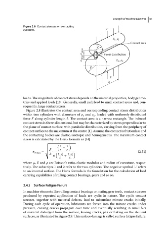
Figure 2.8 Contact stresses on contacting           Strength of Machine Elements  51
                          cylinders.


                          loads. The magnitude of contact stress depends on the material properties, body geome-
                          tries and applied loads [18]. Generally, small radii lead to small contact areas and, con-
                          sequently, large contact stress.
                            Figure 2.8 illustrates the contact area and corresponding contact stress distribution
                          within two cylinders with diameters of    and    , loaded with uniformly distributed
                                                             1     2
                          force F along cylinder length b. The contact area is a narrow rectangle. The induced
                          contact stress is three-dimensional but may be characterized by stress perpendicular to
                          the plane of contact surface, with parabolic distribution, varying from the periphery of
                          contact surface to the maximum at the centre [1]. Assume the contact is frictionless and
                          the contacting bodies are elastic, isotropic and homogeneous. The maximum contact
                          stress is calculated by the Hertz formula as [14]
                                       √
                                              (      )
                                       √       1   1
                                       √         ±
                                       √ F        1     2
                                       √
                                  Hmax  = √  •  (      )                                     (2.51)
                                         b    1−   2  1−    2
                                                 1  +  2
                                               E 1   E 2
                          where   , E and    are Poisson’s ratio, elastic modulus and radius of curvature, respec-
                          tively. The subscripts 1 and 2 refer to the two cylinders. The negative symbol ‘–’ refers
                          to an internal surface. The Hertz formula is the foundation for the calculation of load
                          carrying capabilities of rolling contact bearings, gears and so on.
                          2.4.2  Surface Fatigue Failure

                          In machine elements like rolling contact bearings or mating gear teeth, contact stresses
                          produced by repeated application of loads are cyclic in nature. The cyclic contact
                          stresses, together with material defects, lead to subsurface minute cracks initially.
                          During each cycle of operation, lubricants are forced into the minute cracks under
                          pressure, causing cracks propagate over time and eventually resulting in small bits
                          of material dislodged from the surface, leaving cracks, pits or flaking on the element
                          surfaces, as illustrated in Figure 2.9. This surface damage is called surface fatigue failure.