
Page 407 - Analysis, Synthesis and Design of Chemical Processes, Third Edition
P. 407
simulation in terms of an output report. Often, graphical displays of tower profiles, heating
curves, and a variety of other useful process data can be produced.
6. Flowsheet Solver: This portion of the simulator controls the sequence of the calculations and the
overall convergence of the simulation.
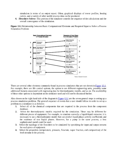
Figure 13.1 Relationship between Basic Computational Elements and Required Input to Solve a Process
Simulation Problem
There are several other elements commonly found in process simulators that are not shown in Figure 13.1.
For example, there are file control options, the option to use different engineering units, possibly some
additional features associated with regressing data for thermodynamic models, and so on. The availability
of these other options is dependent on the simulator used and will not be discussed further.
Also shown on the right-hand side of the diagram in Figure 13.1 are the seven general steps to setting up a
process simulation problem. The general sequence of events that a user should follow in order to set up a
problem on a simulator is as follows:
1. Select all of the chemical components that are required in the process from the component
database.
2. Select the thermodynamic models required for the simulation. These may be different for
different pieces of equipment. For example, to simulate correctly a liquid-liquid extractor, it is
necessary to use a thermodynamic model that can predict liquid-phase activity coefficients and
the existence of two liquid phases. However, for a pump in the same process, a less
sophisticated model could be used.
3. Select the topology of the flowsheet to be simulated by specifying the input and output streams
for each piece of equipment.
4. Select the properties (temperature, pressure, flowrate, vapor fraction, and composition) of the
feed streams to the process.