
Page 412 - Analysis, Synthesis and Design of Chemical Processes, Third Edition
P. 412
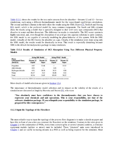
Table E13.1 shows the results for the two outlet streams from the absorber—Streams 12 and 13—for two
                    simulations, each using a different thermodynamic model for the vapor-liquid equilibrium calculations.

                    The second and third columns in the table show the results using the SRK (Soave [7], Redlich and Kwong
                    [8]) model, which is the preferred model for many common components. The fourth and fifth columns
                    show the results using a model that is specially designed to deal with ionic type compounds (HCl) that
                    dissolve in water and then dissociate. The difference in results is remarkable. The HCl-water system is
                    highly non-ideal, and, even though the absorption of an acid gas into aqueous solutions is quite common,
                    the SRK model is not capable of correctly modeling the phase behavior of this system. With the SRK
                    model, virtually all the HCl leaves the absorber as a gas. Clearly, if the simulation were done using only
                    the SRK model, the results would be drastically in error. This result is especially disturbing because
                    SRK is the default thermodynamics package in many simulators.


                    Table  E13.1  Results  of  Simulation  of  HCl  Absorption  Using  Two  Different  Physical  Property
                    Models


                    More details of model selection are given in Section 13.4.


                    The  importance  of  thermodynamic  model  selection  and  its  impact  on  the  validity  of  the  results  of  a
                    simulation are discussed at length by Horwitz and Nocera [9], who warn


                          “You  absolutely  must  have  confidence  in  the  thermodynamics  that  you  have  chosen  to
                          represent  your  chemicals  and  unit  operations.  This  is  your  responsibility,  not  that  of  the
                          software simulation package. If you relinquish your responsibility to the simulation package, be
                          prepared for dire consequences.”


                    13.2.3 Input the Topology of the Flowsheet


                    The most reliable way to input the topology of the process flow diagram is to make a sketch on paper and
                    have this in front of you when you construct the flowsheet on the simulator. Contrary to the rules given in
                    Chapter 1 on the construction of PFDs, every time a stream splits or several streams combine, a simulator
                    equipment  module  (splitter  or  mixer)  must  be  included.  These  “phantom”  units  were  introduced  in
                    Chapter 5 and are useful in tracing streams in a PFD as well as being required for the simulator. Most