
Page 414 - Analysis, Synthesis and Design of Chemical Processes, Third Edition
P. 414
of stages in the extractor, case studies in which the number of stages are varied can be performed, and this
information used to determine the correct number of stages required to obtain the desired recovery of
98%. In other cases, such as a plug flow reactor module, the simulator can solve the design problem
directly—that is, calculate the amount of catalyst required to carry out the desired reaction. Therefore,
before one starts a process simulation it is important to know what equipment parameters must be
specified in order for the process to be simulated.
There are essentially two levels at which a process simulation can be carried out. The first level, Level 1,
is one in which the minimum data are supplied in order for the material and energy balances to be
obtained. The second level, Level 2, is one in which the simulator is used to do as many of the design
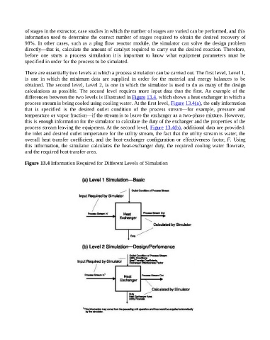
calculations as possible. The second level requires more input data than the first. An example of the
differences between the two levels is illustrated in Figure 13.4, which shows a heat exchanger in which a
process stream is being cooled using cooling water. At the first level, Figure 13.4(a), the only information
that is specified is the desired outlet condition of the process stream—for example, pressure and
temperature or vapor fraction—if the stream is to leave the exchanger as a two-phase mixture. However,
this is enough information for the simulator to calculate the duty of the exchanger and the properties of the
process stream leaving the equipment. At the second level, Figure 13.4(b), additional data are provided:
the inlet and desired outlet temperature for the utility stream, the fact that the utility stream is water, the
overall heat transfer coefficient, and the heat-exchanger configuration or effectiveness factor, F. Using
this information, the simulator calculates the heat-exchanger duty, the required cooling water flowrate,
and the required heat transfer area.
Figure 13.4 Information Required for Different Levels of Simulation