
Page 75 - Analysis, Synthesis and Design of Chemical Processes, Third Edition
P. 75
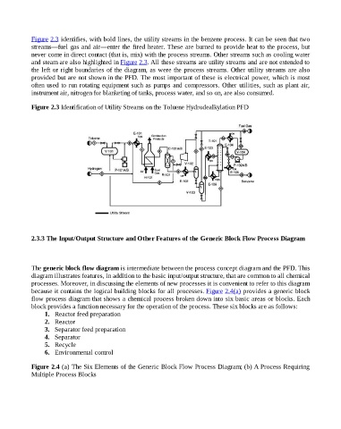
Figure 2.3 identifies, with bold lines, the utility streams in the benzene process. It can be seen that two
                    streams—fuel gas and air—enter the fired heater. These are burned to provide heat to the process, but
                    never come in direct contact (that is, mix) with the process streams. Other streams such as cooling water
                    and steam are also highlighted in Figure 2.3. All these streams are utility streams and are not extended to
                    the left or right boundaries of the diagram, as were the process streams. Other utility streams are also
                    provided but are not shown in the PFD. The most important of these is electrical power, which is most
                    often used to run rotating equipment such as pumps and compressors. Other utilities, such as plant air,
                    instrument air, nitrogen for blanketing of tanks, process water, and so on, are also consumed.


                    Figure 2.3 Identification of Utility Streams on the Toluene Hydrodealkylation PFD


                    2.3.3 The Input/Output Structure and Other Features of the Generic Block Flow Process Diagram


                    The generic block flow diagram is intermediate between the process concept diagram and the PFD. This
                    diagram illustrates features, in addition to the basic input/output structure, that are common to all chemical
                    processes. Moreover, in discussing the elements of new processes it is convenient to refer to this diagram
                    because it contains the logical building blocks for all processes. Figure 2.4(a) provides a generic block
                    flow process diagram that shows a chemical process broken down into six basic areas or blocks. Each
                    block provides a function necessary for the operation of the process. These six blocks are as follows:
                          1.   Reactor feed preparation
                          2.   Reactor
                          3.   Separator feed preparation
                          4.   Separator
                          5.   Recycle
                          6.   Environmental control


                    Figure 2.4 (a) The Six Elements of the Generic Block Flow Process Diagram; (b) A Process Requiring
                    Multiple Process Blocks