
Page 116 - Analytical Electrochemistry 2d Ed - Jospeh Wang
P. 116
4-1 ELECTROCHEMICAL CELLS 101
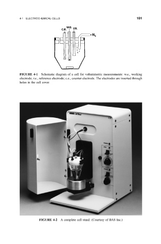
FIGURE 4-1 Schematic diagram of a cell for voltammetric measurements: w.e., working
electrode; r.e., reference electrode; c.e., counter electrode. The electrodes are inserted through
holes in the cell cover.
FIGURE 4-2 A complete cell stand. (Courtesy of BAS Inc.)