
Page 120 - Analytical Electrochemistry 2d Ed - Jospeh Wang
P. 120
4-4 INSTRUMENTATION 105
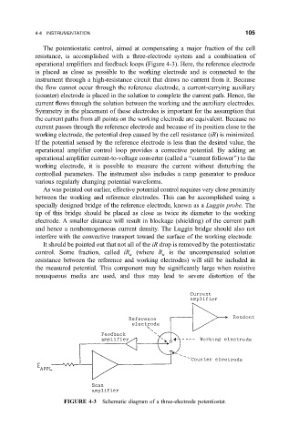
The potentiostatic control, aimed at compensating a major fraction of the cell
resistance, is accomplished with a three-electrode system and a combination of
operational ampli®ers and feedback loops (Figure 4-3). Here, the reference electrode
is placed as close as possible to the working electrode and is connected to the
instrument through a high-resistance circuit that draws no current from it. Because
the ¯ow cannot occur through the reference electrode, a current-carrying auxiliary
(counter) electrode is placed in the solution to complete the current path. Hence, the
current ¯ows through the solution between the working and the auxiliary electrodes.
Symmetry in the placement of these electrodes is important for the assumption that
the current paths from all points on the working electrode are equivalent. Because no
current passes through the reference electrode and because of its position close to the
working electrode, the potential drop caused by the cell resistance (iR) is minimized.
If the potential sensed by the reference electrode is less than the desired value, the
operational ampli®er control loop provides a corrective potential. By adding an
operational ampli®er current-to-voltage converter (called a ``current follower'') to the
working electrode, it is possible to measure the current without disturbing the
controlled parameters. The instrument also includes a ramp generator to produce
various regularly changing potential waveforms.
As was pointed out earlier, effective potential control requires very close proximity
between the working and reference electrodes. This can be accomplished using a
specially designed bridge of the reference electrode, known as a Luggin probe.The
tip of this bridge should be placed as close as twice its diameter to the working
electrode. A smaller distance will result in blockage (shielding) of the current path
and hence a nonhomogeneous current density. The Luggin bridge should also not
interfere with the convective transport toward the surface of the working electrode.
It should be pointed out that not all of the iR drop is removed by the potentiostatic
control. Some fraction, called iR u (where R u is the uncompensated solution
resistance between the reference and working electrodes) will still be included in
the measured potential. This component may be signi®cantly large when resistive
nonaqueous media are used, and thus may lead to severe distortion of the
FIGURE 4-3 Schematic diagram of a three-electrode potentiostat.