
Page 17 - Analytical Electrochemistry 2d Ed - Jospeh Wang
P. 17
2 FUNDAMENTAL CONCEPTS
to the target analyte(s) and is thus termed the indicator (or working) electrode. The
second one, termed the reference electrode, is of constant potential (that is,
independent of the properties of the solution). Electrochemical cells can be classi®ed
as electrolytic (when they consume electricity from an external source) or galvanic
(if they are used to produce electrical energy).
Potentiometry (discussed in Chapter 5), which is of great practical importance, is
a static (zero current) technique in which the information about the sample
composition is obtained from measurement of the potential established across a
membrane. Different types of membrane materials, possessing different ion-recogni-
tion processes, have been developed to impart high selectivity. The resulting
potentiometric probes have thus been widely used for several decades for direct
monitoring of ionic species such as protons or calcium, ¯uoride, and potassium ions
in complex samples.
Controlled-potential (potentiostatic) techniques deal with the study of charge-
transfer processes at the electrode±solution interface, and are based on dynamic (no
zero current) situations. Here, the electrode potential is being used to derive an
electron-transfer reaction and the resultant current is measured. The role of the
potential is analogous to that of the wavelength in optical measurements. Such a
controllable parameter can be viewed as ``electron pressure,'' which forces the
chemical species to gain or lose an electron (reduction or oxidation, respectively).
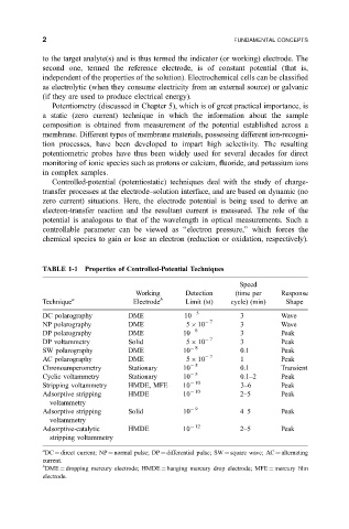
TABLE 1-1 Properties of Controlled-Potential Techniques
Speed
Working Detection (time per Response
Technique a Electrode b Limit (M) cycle) (min) Shape
DC polarography DME 10 5 3 Wave
NP polarography DME 5 10 7 3 Wave
DP polarography DME 10 8 3 Peak
DP voltammetry Solid 5 10 7 3 Peak
SW polarography DME 10 8 0.1 Peak
AC polarography DME 5 10 7 1 Peak
Chronoamperometry Stationary 10 5 0.1 Transient
Cyclic voltammetry Stationary 10 5 0.1±2 Peak
Stripping voltammetry HMDE, MFE 10 10 3±6 Peak
Adsorptive stripping HMDE 10 10 2±5 Peak
voltammetry
Adsorptive stripping Solid 10 9 4±5 Peak
voltammetry
Adsorptive-catalytic HMDE 10 12 2±5 Peak
stripping voltammetry
a
DC direct current; NP normal pulse; DP differential pulse; SW square wave; AC alternating
current.
b
DME dropping mercury electrode; HMDE hanging mercury drop electrode; MFE mercury ®lm
electrode.