
Page 224 - Anatomy of a Robot
P. 224
08_200256_CH08/Bergren 4/10/03 4:39 PM Page 209
Input
Tap Register Tap Coefficient DIGITAL SIGNAL PROCESSING (DSP) 209
X
Tap Register Tap Coefficient
X
Tap Register Tap Coefficient
X
Tap Register Tap Coefficient
X
+
Tap Register Tap Coefficient
X Output
Tap Register Tap Coefficient
X
Tap Register Tap Coefficient
X
Tap Register Tap Coefficient
X
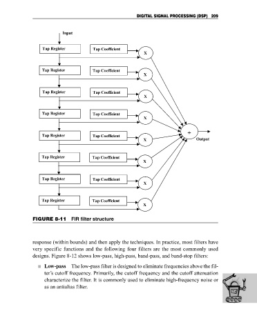
FIGURE 8-11 FIR filter structure
response (within bounds) and then apply the techniques. In practice, most filters have
very specific functions and the following four filters are the most commonly used
designs. Figure 8-12 shows low-pass, high-pass, band-pass, and band-stop filters:
Low-pass The low-pass filter is designed to eliminate frequencies above the fil-
ter’s cutoff frequency. Primarily, the cutoff frequency and the cutoff attenuation
characterize the filter. It is commonly used to eliminate high-frequency noise or
as an antialias filter.