
Page 225 - Anatomy of a Robot
P. 225
08_200256_CH08/Bergren 4/10/03 4:39 PM Page 210
210 CHAPTER EIGHT
Low-Pass Filter
High-Pass Filter Band-Pass Filter
Band-Stop Filter
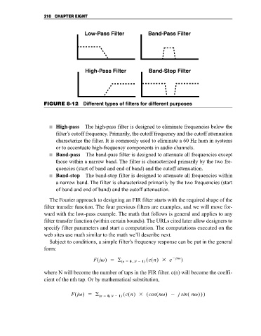
FIGURE 8-12 Different types of filters for different purposes
High-pass The high-pass filter is designed to eliminate frequencies below the
filter’s cutoff frequency. Primarily, the cutoff frequency and the cutoff attenuation
characterize the filter. It is commonly used to eliminate a 60 Hz hum in systems
or to accentuate high-frequency components in audio channels.
Band-pass The band-pass filter is designed to attenuate all frequencies except
those within a narrow band. The filter is characterized primarily by the two fre-
quencies (start of band and end of band) and the cutoff attenuation.
Band-stop The band-stop filter is designed to attenuate all frequencies within
a narrow band. The filter is characterized primarily by the two frequencies (start
of band and end of band) and the cutoff attenuation.
The Fourier approach to designing an FIR filter starts with the required shape of the
filter transfer function. The four previous filters are examples, and we will move for-
ward with the low-pass example. The math that follows is general and applies to any
filter transfer function (within certain bounds). The URLs cited later allow designers to
specify filter parameters and start a computation. The computations executed on the
web sites use math similar to the math we’ll describe next.
Subject to conditions, a simple filter’s frequency response can be put in the general
form:
F(jv) (n 0 , N 1) (c(n) e jnv )
where N will become the number of taps in the FIR filter. c(n) will become the coeffi-
cient of the nth tap. Or by mathematical substitution,
F(jv) (n 0, N 1) (c(n) (cos(nv) j sin( nv)))