
Page 227 - Anatomy of a Robot
P. 227
08_200256_CH08/Bergren 4/10/03 4:39 PM Page 212
212 CHAPTER EIGHT
This means the FIR filter can be limited to a specific number of taps based on the win-
dow. Most of these windows keep the center taps (generally with the largest coeffi-
cients) and decrease the size of the window to zero as it reaches the edge coefficients.
The windows have well-known names and predictable effects on the filter. They are
automatically added to the calculations since a window must be used to have a calcu-
lation at all. The URLs that follow allow us to perform calculations using JAVA tools.
They have the windows built in to the Java tool that computes the coefficients and shows
you the resultant filter transfer function. Each window has its strength and weaknesses,
but we must choose a window for every calculation. Some of the windows are outlined
here. In each case, we show the shape of the window. In addition, we show a FIR filter
built with all the same parameters except for the choice of window type.
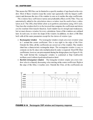
Rectangular window The rectangular window simply sets every window value
to 1 around the center coefficient. This is true right to the edge of the filter.
Outside the filter, all the coefficients are zeroed out of the window. The window
chart has a characteristic rectangular shape. The rectangular window is easy to
compute on the fly since only multiplication by unity is required. Most FIR filter
coefficients, however, are precomputed during the design phase (see Figure 8-14).
The math behind the rectangular window is explained at http://mathworld.
wolfram.com/UniformApodizationFunction.html.
Bartlett (triangular) window The triangular window simply sets every win-
dow value to a linearly decreasing value starting at the center coefficient. Right at
the edge of the filter, it reaches zero. Outside the filter, all the coefficients are
0.0 0.1 0.2 0.3 0.4 0.5
0 db
-20 db
-40 db
-60 db
-80 db
-100 db
-120 db
FIGURE 8-14 Rectangular DSP window and frequency response