
Page 232 - Anatomy of a Robot
P. 232
08_200256_CH08/Bergren 4/10/03 4:39 PM Page 217
DIGITAL SIGNAL PROCESSING (DSP) 217
observe a significant response from the filter above the sampling frequency, we
should reexamine the integrity of the antialias filter design. The output sine waves
should be clean and well behaved.
The FIR Filter FAQ site contains a thorough explanation of FIR filters and lists a few
more tests that can be run (www.dspguru.com/info/faqs/firfaq.htm). The following sites
describe FIR filters and have various tools for designing them:
http://web.mit.edu/6.555/www/fir.html
www.nauticom.net/www/jdtaft/fir.htm
www.filter-solutions.com/FIR.html#asinxx
INFINITE IMPULSE RESPONSE (IIR) FILTERS
Okay, now that we’ve wrestled FIR filters to the ground, here’s another wrinkle. Infinite
Impulse Response (IIR) filters are another option for designing a DSP filter. Although
a FIR filter passes signals once through in a fixed, linear sequence, IIR filters have feed-
back loops. Output signals, even intermediate signals, are fed backwards during the pro-
cessing. This has a few implications:
IIR filters are shorter. Think for a minute about the path that data takes through
an IIR filter. Instead of going through once, like in a FIR filter, the data may be
fed back a few times. These extra loops through the IIR filters act almost as exten-
sions of the filter. The result is that an IIR filter can get similar results with much
fewer taps. Let’s look at a rough comparison.
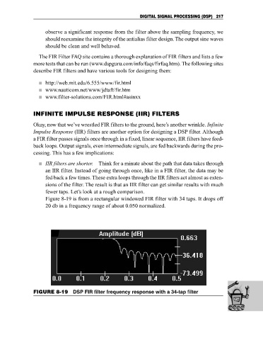
Figure 8-19 is from a rectangular windowed FIR filter with 34 taps. It drops off
20 db in a frequency range of about 0.050 normalized.
FIGURE 8-19 DSP FIR filter frequency response with a 34-tap filter