
Page 234 - Anatomy of a Robot
P. 234
08_200256_CH08/Bergren 4/10/03 4:39 PM Page 219
DIGITAL SIGNAL PROCESSING (DSP) 219
Diagrams for the design of IIR second-order filters can be found at
http://spuc.sourceforge.net/iir_2nd.html and at www.nauticom.net/www/jdtaft/
biquad_section.htm.
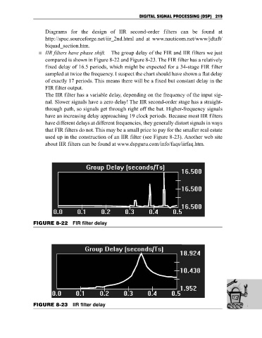
IIR filters have phase shift. The group delay of the FIR and IIR filters we just
compared is shown in Figure 8-22 and Figure 8-23. The FIR filter has a relatively
fixed delay of 16.5 periods, which might be expected for a 34-stage FIR filter
sampled at twice the frequency. I suspect the chart should have shown a flat delay
of exactly 17 periods. This means there will be a fixed but constant delay in the
FIR filter output.
The IIR filter has a variable delay, depending on the frequency of the input sig-
nal. Slower signals have a zero delay! The IIR second-order stage has a straight-
through path, so signals get through right off the bat. Higher-frequency signals
have an increasing delay approaching 19 clock periods. Because most IIR filters
have different delays at different frequencies, they generally distort signals in ways
that FIR filters do not. This may be a small price to pay for the smaller real estate
used up in the construction of an IIR filter (see Figure 8-23). Another web site
about IIR filters can be found at www.dspguru.com/info/faqs/iirfaq.htm.
FIGURE 8-22 FIR filter delay
FIGURE 8-23 IIR filter delay