
Page 245 - Anatomy of a Robot
P. 245
09_200256_CH09/Bergren 4/17/03 11:24 AM Page 230
230 CHAPTER NINE
Robustness
Some pulse-coding schemes have built-in mechanisms for avoid-
ing and/or detecting errors.
The following PDFs and web site provide a good summary of the advantages and dis-
advantages of various coding methods:
www.elec.mq.edu.au/ cl/files_pdf/elec321/lect_lc.pdf
http://murray.newcastle.edu.au/users/staff/jkhan/lec08.pdf
www.cise.ufl.edu/ nemo/cen4500/coding.html
PULSE DISTORTION: MATCHING FILTERS
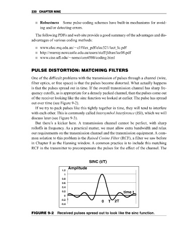
One of the difficult problems with the transmission of pulses through a channel (wire,
fiber optics, or free space) is that the pulses become distorted. What actually happens
is that the pulses spread out in time. If the overall transmission channel has sharp fre-
quency cutoffs, as is appropriate for a densely packed channel, then the pulses come out
of the receiver looking like the sinc function we looked at earlier. The pulse has spread
out over time (see Figure 9-2).
If we try to pack pulses like this tightly together in time, they will tend to interfere
with each other. This is commonly called Intersymbol Interference (ISI), which we will
discuss later (see Figure 9-3).
But there’s a kicker here. A transmission channel cannot be perfect, with sharp
rolloffs in frequency. As a practical matter, we must allow extra bandwidth and relax
our requirements on the transmission channel and the transmission equipment. A com-
mon solution to this problem is the Raised Cosine Filter (RCF), a filter we saw before
in Chapter 8 as the Hanning window. A common practice is to include this matching
RCF in the transmitter to precompensate the pulses for the effect of the channel. The
SINC (t/T)
Amplitude
1.2
1
0.8
0.6
0.4
0.2 time t
0
-0.2 1
0 T 2T
-0.4
FIGURE 9-2 Received pulses spread out to look like the sinc function.