
Page 152 - Antennas for Base Stations in Wireless Communications
P. 152
Antennas for Mobile Communications: CDMA, GSM, and WCDMA 125
the simple antenna structure. Indeed, the impedance bandwidths
(RL < –14 dB) obtained by simulation and measurement are identi-
cal, which are 21% (0.782–0.965 GHz) in the lower band and 25.3%
(1.69–2.18 GHz) in the upper band. Also, in Figure 3.22 the simulated
and measured peak gains are around 8 to 9 dBi in both bands.
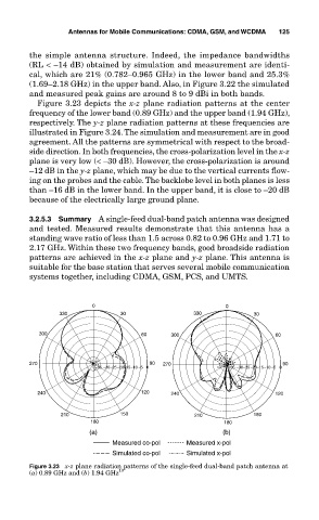
Figure 3.23 depicts the x-z plane radiation patterns at the center
frequency of the lower band (0.89 GHz) and the upper band (1.94 GHz),
respectively. The y-z plane radiation patterns at these frequencies are
illustrated in Figure 3.24. The simulation and measurement are in good
agreement. All the patterns are symmetrical with respect to the broad-
side direction. In both frequencies, the cross-polarization level in the x-z
plane is very low (< –30 dB). However, the cross-polarization is around
–12 dB in the y-z plane, which may be due to the vertical currents flow-
ing on the probes and the cable. The backlobe level in both planes is less
than –16 dB in the lower band. In the upper band, it is close to –20 dB
because of the electrically large ground plane.
3.2.5.3 Summary A single-feed dual-band patch antenna was designed
and tested. Measured results demonstrate that this antenna has a
standing wave ratio of less than 1.5 across 0.82 to 0.96 GHz and 1.71 to
2.17 GHz. Within these two frequency bands, good broadside radiation
patterns are achieved in the x-z plane and y-z plane. This antenna is
suitable for the base station that serves several mobile communication
systems together, including CDMA, GSM, PCS, and UMTS.
0 0
330 30 330 30
300 60 300 60
270 90 270 90
−35 −30−25−20−15−10 −5 0 −35 −30−25−20−15−10 −5 0
240 120 240 120
210 150 210 150
180 180
(a) (b)
Measured co-pol Measured x-pol
Simulated co-pol Simulated x-pol
Figure 3.23 x-z plane radiation patterns of the single-feed dual-band patch antenna at
(a) 0.89 GHz and (b) 1.94 GHz 10