
Page 147 - Antennas for Base Stations in Wireless Communications
P. 147
120 Chapter Three
4.5 7
4 6
3.5 5
3 4
SWR Gain (dBi)
2.5 3
2 2
1.5 1
1 0
1.4 1.6 1.8 2 2.2 2.4 2.6 2.8 3
Frequency (GHz)
Simulated Measured
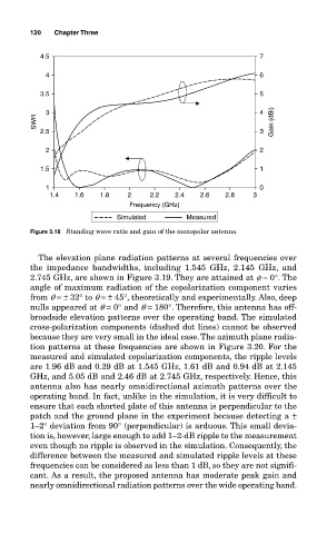
Figure 3.18 Standing wave ratio and gain of the monopolar antenna
The elevation plane radiation patterns at several frequencies over
the impedance bandwidths, including 1.545 GHz, 2.145 GHz, and
2.745 GHz, are shown in Figure 3.19. They are attained at f = 0°. The
angle of maximum radiation of the copolarization component varies
from q = ± 32° to q = ± 45°, theoretically and experimentally. Also, deep
nulls appeared at q = 0° and q = 180°. Therefore, this antenna has off-
broadside elevation patterns over the operating band. The simulated
cross-polarization components (dashed dot lines) cannot be observed
because they are very small in the ideal case. The azimuth plane radia-
tion patterns at these frequencies are shown in Figure 3.20. For the
measured and simulated copolarization components, the ripple levels
are 1.96 dB and 0.29 dB at 1.545 GHz, 1.61 dB and 0.94 dB at 2.145
GHz, and 5.05 dB and 2.46 dB at 2.745 GHz, respectively. Hence, this
antenna also has nearly omnidirectional azimuth patterns over the
operating band. In fact, unlike in the simulation, it is very difficult to
ensure that each shorted plate of this antenna is perpendicular to the
patch and the ground plane in the experiment because detecting a ±
1–2° deviation from 90° (perpendicular) is arduous. This small devia-
tion is, however, large enough to add 1–2-dB ripple to the measurement
even though no ripple is observed in the simulation. Consequently, the
difference between the measured and simulated ripple levels at these
frequencies can be considered as less than 1 dB, so they are not signifi-
cant. As a result, the proposed antenna has moderate peak gain and
nearly omnidirectional radiation patterns over the wide operating band.