
Page 145 - Antennas for Base Stations in Wireless Communications
P. 145
118 Chapter Three
0 0
330 30 330 30
300 60 300 60
270 90 270 90
−35−30−25−20−15−10 −5 0 −35−30−25−20−15−10 −5 0
240 120 240 120
210 150 210 150
180 180
(a) (b)
0 0
330 30 330 30
300 60 300 60
270 90 270 90
−35−30−25−20−15−10 −5 0 −35−30−25−20−15−10 −5 0
240 120 240 120
210 150 210 150
180 180
(c) −45° polarization (d)
+45° polarization
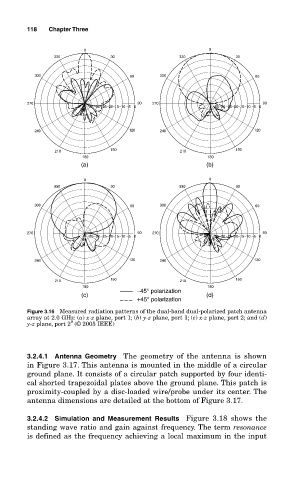
Figure 3.16 Measured radiation patterns of the dual-band dual-polarized patch antenna
array at 2.0 GHz: (a) x-z plane, port 1; (b) y-z plane, port 1; (c) x-z plane, port 2; and (d)
9
y-z plane, port 2 (© 2005 IEEE)
3.2.4.1 Antenna Geometry The geometry of the antenna is shown
in Figure 3.17. This antenna is mounted in the middle of a circular
ground plane. It consists of a circular patch supported by four identi-
cal shorted trapezoidal plates above the ground plane. This patch is
proximity-coupled by a disc-loaded wire/probe under its center. The
antenna dimensions are detailed at the bottom of Figure 3.17.
3.2.4.2 Simulation and Measurement Results Figure 3.18 shows the
standing wave ratio and gain against frequency. The term resonance
is defined as the frequency achieving a local maximum in the input