
Page 140 - Antennas for Base Stations in Wireless Communications
P. 140
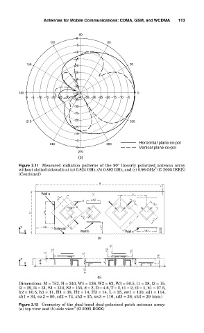
Antennas for Mobile Communications: CDMA, GSM, and WCDMA        113

                                          90
                                         0
                              120                    60
                                        −5
                                        −10
                                        −15
                     150                −20                   30
                                        −25
                                        −30
                                        −35
                  180                   −40                      0
                     0  −5  −10  −15  −20  −25  −30 −35  −40 −35 −30 −25 −20 −15 −10 −5  0
                                        −35
                                        −30
                                        −25
                     210                −20                   330
                                        −15
                                        −10
                                        −5
                              240                    300         Horizontal plane co-pol
                                         0                       Vertical plane co-pol
                                          270
                                          (c)
                  Figure  3.11  Measured  radiation  patterns  of  the  90°  linearly  polarized  antenna  array
                                                                       8
                  without slotted sidewalls at (a) 0.824 GHz, (b) 0.892 GHz, and (c) 0.96 GHz  (© 2005 IEEE)
                  (Continued)

                           Wall a


                   y            Sidewall
                     x                    Wall b            Wall c
                                                 (a)


                   z
                     x


                                                 (b)
                  Dimensions: M = 752, N = 244, W1 = 126, W2 = 62, W3 = 50.5, l1 = 38, l2 = 15,
                  l3 = 29, l4 = 31, S1 = 310, S2 = 155, d = 2, D = 4.6, T = 2, t1 = 2, t2 = 1, h1 = 27.5,
                  h2 = 10.5, h3 = 11, H1 = 38, H2 = 14, H3 = 14, L = 35, sw1 = 130, sd1 = 114,
                  sh1 = 34, sw2 = 80, sd2 = 74, sh2 = 15, sw3 = 116, sd3 = 38, sh3 = 29 (mm)
                  Figure 3.12  Geometry of the dual-band dual-polarized patch antenna array:
                                        9
                  (a) top view and (b) side view  (© 2005 IEEE)