
Page 138 - Antennas for Base Stations in Wireless Communications
P. 138
Antennas for Mobile Communications: CDMA, GSM, and WCDMA 111
90
0
120 60
−5
−10
−15
150 −20 30
−25
−30
−35
180 −40 0
0 −5 −10 −15 −20 −25 −30 −35 −40 −35 −30 −25 −20 −15 −10 −5 0
−35
−30
−25
210 −20 330
−15
−10
−5 Horizontal plane co-pol
240 300 Vertical plane co-pol
0
270
(c)
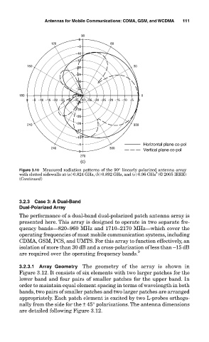
Figure 3.10 Measured radiation patterns of the 90° linearly polarized antenna array
8
with slotted sidewalls at (a) 0.824 GHz, (b) 0.892 GHz, and (c) 0.96 GHz (© 2005 IEEE)
(Continued)
3.2.3 Case 3: A Dual-Band
Dual-Polarized Array
The performance of a dual-band dual-polarized patch antenna array is
presented here. This array is designed to operate in two separate fre-
quency bands—820–960 MHz and 1710–2170 MHz—which cover the
operating frequencies of most mobile communication systems, including
CDMA, GSM, PCS, and UMTS. For this array to function effectively, an
isolation of more than 30 dB and a cross-polarization of less than –15 dB
are required over the operating frequency bands. 9
3.2.3.1 Array Geometry The geometry of the array is shown in
Figure 3.12. It consists of six elements with two larger patches for the
lower band and four pairs of smaller patches for the upper band. In
order to maintain equal element spacing in terms of wavelength in both
bands, two pairs of smaller patches and two larger patches are arranged
appropriately. Each patch element is excited by two L-probes orthogo-
nally from the side for the ± 45° polarizations. The antenna dimensions
are detailed following Figure 3.12.