
Page 141 - Antennas for Base Stations in Wireless Communications
P. 141
114 Chapter Three
3.2.3.2 Isolation Enhancement Probe-fed antennas have the weakness of
a higher cross-polarization level due to strong radiation from the vertical
probes. In the dual-polarization case, these radiations will also increase
the coupling between the two input ports. To solve this issue, two meth-
ods were employed to suppress the input port coupling of the array with
feed networks phase cancellation and adding auxiliary metallic side-
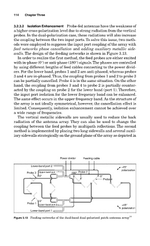
walls. The design of the feeding networks is shown in Figure 3.13.
In order to realize the first method, the feed probes are either excited
with in-phase (0°) or anti-phase (180°) signals. The phases are controlled
by using different lengths of feed cables connecting to the power divid-
ers. For the lower band, probes 1 and 2 are anti-phased, whereas probes
3 and 4 are in-phased. Thus, the coupling from probes 1 and 2 to probe 3
can be partially cancelled. Probe 4 is in the same situation. On the other
hand, the coupling from probes 3 and 4 to probe 2 is partially counter-
acted by the coupling on probe 2 for the lower band (port 1). Therefore,
the input port isolation for the lower frequency band can be enhanced.
The same effect occurs in the upper frequency band. As the structure of
the array is not ideally symmetrical, however, the cancellation effect is
limited. Consequently, isolation enhancement cannot be achieved over
a wide range of frequencies.
The vertical metallic sidewalls are usually used to reduce the back
radiation of the antenna array. They can also be used to change the
coupling between the feed probes by multipath reflections. The second
method is implemented by placing two long sidewalls and several auxil-
iary sidewalls strategically on the ground plane of the array as depicted in
Power divider Feeding cable
Lower-band port 2 −45°
polarization
Probe 3 Upper-band port 1 180° Probe 2
0° 0°
Probe 4
0°
Probe 1
Upper-band port 2 +45°
polarization
Lower-band port 1
Figure 3.13 Feeding networks of the dual-band dual-polarized patch antenna array 10