
Page 133 - Antennas for Base Stations in Wireless Communications
P. 133
106 Chapter Three
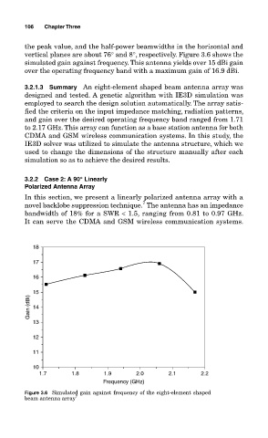
the peak value, and the half-power beamwidths in the horizontal and
vertical planes are about 76° and 8°, respectively. Figure 3.6 shows the
simulated gain against frequency. This antenna yields over 15 dBi gain
over the operating frequency band with a maximum gain of 16.9 dBi.
3.2.1.3 Summary An eight-element shaped beam antenna array was
designed and tested. A genetic algorithm with IE3D simulation was
employed to search the design solution automatically. The array satis-
fied the criteria on the input impedance matching, radiation patterns,
and gain over the desired operating frequency band ranged from 1.71
to 2.17 GHz. This array can function as a base station antenna for both
CDMA and GSM wireless communication systems. In this study, the
IE3D solver was utilized to simulate the antenna structure, which we
used to change the dimensions of the structure manually after each
simulation so as to achieve the desired results.
3.2.2 Case 2: A 90ç Linearly
Polarized Antenna Array
In this section, we present a linearly polarized antenna array with a
7
novel backlobe suppression technique. The antenna has an impedance
bandwidth of 18% for a SWR < 1.5, ranging from 0.81 to 0.97 GHz.
It can serve the CDMA and GSM wireless communication systems.
18
17
16
15
Gain (dBi) 14
13
12
11
10
1.7 1.8 1.9 2.0 2.1 2.2
Frequency (GHz)
Figure 3.6 Simulated gain against frequency of the eight-element shaped
beam antenna array 7