Page 130 - Antennas for Base Stations in Wireless Communications
P. 130

Antennas for Mobile Communications: CDMA, GSM, and WCDMA        103

                             dB[S(1,1)]   dB[S(2,2)]   dB[S(3,3)]    dB[S(4,4)]
                             dB[S(5,5)]   dB[S(6,6)]   dB[S(7,7)]    dB[S(8,8)]
                      −9.5                                                    −9.5
                      −10                                                     −10
                     −10.5                                                    −10.5
                      −11                                                     −11
                     −11.5                                                    −11.5
                      −12                                                     −12
                    dB  −12.5                                                 −12.5  dB
                      −13                                                     −13
                     −13.5                                                    −13.5
                      −14                                                     −14
                     −14.5                                                    −14.5
                      −15                                                     −15
                     −15.5                                                    −15.5
                       1.65  1.7  1.75  1.8  1.85  1.9  1.95  2  2.05  2.1  2.15  2.2
                                             Frequency (GHz)
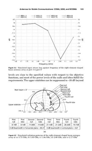
                  Figure 3.4  Simulated input return loss against frequency of the eight-element shaped
                  beam antenna array at port 1 to port 8 7
                  levels are close to the specified values with respect to the objective
                  functions, and most of the power levels of the nulls and lobes fulfill the
                  requirements. The upper sidelobes can be suppressed to −20 dB beyond

                                                               First null
                                                               First lobe
                                                 0.0
                        Main beam = 0°                         Second null
                                       30.0               30.0  Second lobe
                                                                 Third null
                                                                 Third lobe
                                                                   Fourth null
                                60.0                              60.0
                                                                    Fourth lobe
                  Upper sidelobe


                           (180–ϕ)                                   ϕ
                               0.0  −10.0  −20.0  −30.0  −30.0  −20.0  −10.0  0.0


                     First   First  Second   Second   Third  Third  Fourth   Fourth
                      null   lobe    null   lobe    null    lobe    null   lobe
                    −9.7dB  −9.1dB  −14.9dB  −14.6dB  −21.4dB  −21.2dB  −26.2dB  −19.7dB
                   3-dB beamwidth in horizontal plane = 80.3°  3-dB beamwidth in vertical plane = 9.8°
                                                 (a)
                  Figure 3.5  Simulated radiation patterns of the eight-element shaped beam antenna
                  array at (a) 1.71 GHz, (b) 1.83 GHz, (c) 1.94 GHz, (d) 2.06 GHz, and (e) 2.17 GHz 7
   125   126   127   128   129   130   131   132   133   134   135