
Page 131 - Antennas for Base Stations in Wireless Communications
P. 131
104 Chapter Three
First null
First lobe
0.0 Second null
Main beam = 0°
30.0 30.0 Second lobe
Third null
Third lobe
Fourth null
60.0 60.0
Fourth lobe
Upper sidelobe
(180–ϕ) ϕ
0.0 −10.0 −20.0 −30.0 −30.0 −20.0 −10.0 0.0
First First Second Second Third Third Fourth Fourth
null lobe null lobe null lobe null lobe
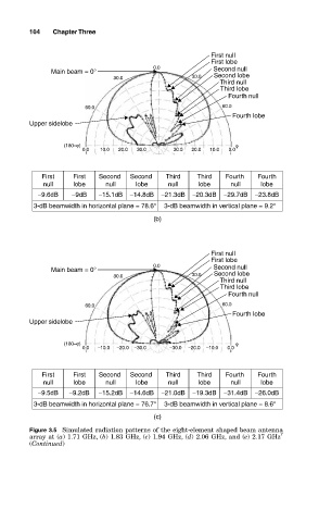
−9.6dB −9dB −15.1dB −14.8dB −21.3dB −20.3dB −29.7dB −23.8dB
3-dB beamwidth in horizontal plane = 78.6° 3-dB beamwidth in vertical plane = 9.2°
(b)
First null
First lobe
0.0 Second null
Main beam = 0°
30.0 30.0 Second lobe
Third null
Third lobe
Fourth null
60.0 60.0
Fourth lobe
Upper sidelobe
(180–ϕ) ϕ
0.0 −10.0 −20.0 −30.0 −30.0 −20.0 −10.0 0.0
First First Second Second Third Third Fourth Fourth
null lobe null lobe null lobe null lobe
−9.5dB −9.2dB −15.2dB −14.6dB −21.0dB −19.3dB −31.4dB −26.0dB
3-dB beamwidth in horizontal plane = 76.7° 3-dB beamwidth in vertical plane = 8.6°
(c)
Figure 3.5 Simulated radiation patterns of the eight-element shaped beam antenna
7
array at (a) 1.71 GHz, (b) 1.83 GHz, (c) 1.94 GHz, (d) 2.06 GHz, and (e) 2.17 GHz
(Continued)